EasyManuals Logo

Cisco C1121-4P User Manual

Cisco C1121-4P
96 pages
To Next Page IconTo Next Page
To Previous Page IconTo Previous Page
Page #65 background imageLoading...
Page #65 background image
Step 3 Disconnect all port cables connected to the router. Ensure that you do not work on the router with cables still attached to
the router in the event of lightning or surges.
Step 4 Place the chassis on a flat surface.
Step 5 Remove the 14 cover screws on the two sides of the router cover. See figure.
Step 6 Slide the cover from bezel side to I/O side until it stops.
Step 7 Pull the cover vertically to disengage from the chassis.
Replace the Cover
To replace the cover, do these steps:
The covers are an integral part of the safety design of the product. Do not operate the unit without the covers
installed. Statement 1077.
Warning
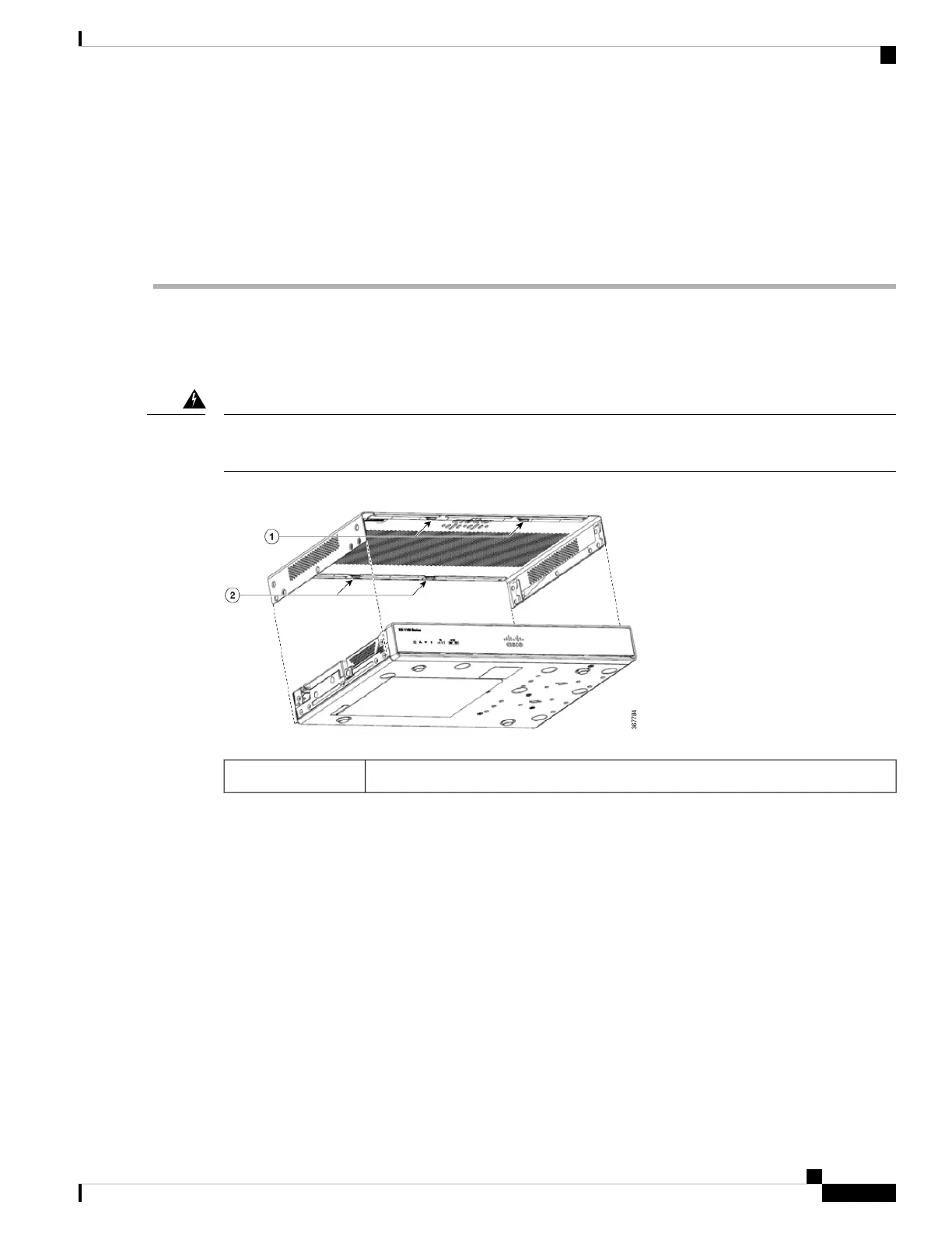
Replace the 14 screws on either side of the cover.1 and 2
Hardware Installation Guide for the Cisco 1000 Series Integrated Services Router
59
Install and Upgrade Internal Modules and Field Replaceable Units
Replace the Cover

Table of Contents

Questions and Answers:

Question and Answer IconNeed help?

Do you have a question about the Cisco C1121-4P and is the answer not in the manual?

Cisco C1121-4P Specifications

General IconGeneral
LAN Ports4
Integrated WirelessNo
Form FactorDesktop
Product TypeRouter
Connectivity TechnologyWired
Data Link ProtocolEthernet, Fast Ethernet, Gigabit Ethernet
Ports Qty4
Power Over Ethernet (PoE)Yes
Routing ProtocolOSPF, BGP, EIGRP
Remote Management ProtocolSNMP
Encryption AlgorithmAES, 3DES, DES
FeaturesFirewall, VPN support
Compliant StandardsIEEE 802.3, IEEE 802.3u
TypeRouter
PoE StandardsIEEE 802.3af
Power SupplyExternal AC adapter
Operating Temperature32°F to 104°F (0°C to 40°C)
Storage Temperature-4°F to 149°F (-20°C to 65°C)
Humidity10 - 95% (non-condensing)
Network/Transport ProtocolDHCP

Related product manuals