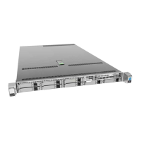
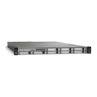
The Cisco C880 M4 Storage Subsystem is a passive, 2-height unit (HU) system designed for expanding hard disk capacity and data management in 19-inch rack infrastructures. This Service Supplement provides detailed information for specialist personnel on replacing non-hot-pluggable components and offers an overview of the system's cabling.
Function Description:
The storage subsystem serves as a direct attachment for managing data or increasing the hard disk capacity of connected servers. Its passive nature implies that it relies on external servers for active data processing and management, primarily functioning as a storage expansion unit. The 2HU form factor ensures it meets requirements for both compactness and maximum hard disk capacity within standard 19-inch rack environments.
Important Technical Specifications:
- Form Factor: 2 Height Units (HU) for 19-inch rack infrastructures.
- Component Type: Passive storage system.
- Connectivity: Utilizes SAS (Serial Attached SCSI) expander modules for connection to RAID controllers of servers.
- Cabling: External SAS connection cables are available in various lengths (0.75m, 2.0m, 4.0m, 6.0m - planned) with two SFF8088 plugs.
- Daisy-chaining: A maximum of three storage subsystems can be daisy-chained to a single RAID controller port, allowing for significant storage expansion.
- Hot-plug Components: The operating manual covers the installation and removal of hot-plug power supply units and hot-plug HDD modules.
- Non-hot-pluggable Components: The SAS expander module, LED display, and backplane are explicitly stated as NOT hot-replaceable, requiring system shutdown for replacement.
Usage Features:
The Cisco C880 M4 is designed for straightforward integration into existing server environments to augment storage capabilities.
- Rack Mounting: The system is intended for mounting in 19-inch racks. Important safety notes regarding rack mounting include the requirement for at least two people due to weight and size, proper anti-tilt bracket installation, and limiting the number of units pulled out simultaneously to prevent tipping.
- Environmental Considerations: The device should be transported in its original packaging. Plastic housing parts should ideally remain free of user-applied labels to facilitate recycling. The device must be disposed of according to European directive 2002/96/EC (WEEE).
- Safety: Users must familiarize themselves with safety instructions, including those related to electrical connections, cable routing to prevent hazards, and avoiding data transmission cable connections during thunderstorms. It is crucial to connect the server and storage subsystem to the same power supply distributor to prevent data loss during power outages. Proper operation requires slot covers in all vacant slots and the housing cover to be fitted for cooling, fire protection, and RFI suppression.
- CE Conformity: The device complies with EC directives 2004/108/EEC (Electromagnetic Compatibility) and 2006/95/EEC (Low-Voltage Directive), indicated by the CE certificate label.
- RFI Suppression: All connected equipment must comply with EC directive 89/336/EEC for radio noise suppression. The C880 M4 is classified as "Class A" equipment, meaning it may cause interference in residential areas, and users may need to take corrective measures.
Maintenance Features:
Maintenance activities, particularly component replacement, are strictly for specialist personnel with technical training.
- Preparation for Component Replacement: Before replacing non-hot-pluggable components, the connected server and storage subsystem must be shut down and switched off. Both power plugs of the storage subsystem must be unplugged from the mains. All SAS cables must be disconnected from the SAS expander module, with a record kept for correct reconnection.
- Replacing the SAS Expander Module: This is not a hot-replaceable component. The process involves releasing ejector levers on both sides and pulling the unit out halfway, then fully removing it while supporting the bottom. Installation is the reverse process.
- Replacing the LED Display: This is also not a hot-replaceable component. The procedure includes loosening a knurled thumb screw that fastens the bezel, removing the bezel, carefully disconnecting the flexible flat cable (FFC) by lifting its lever, removing the connector, undoing two screws, and finally removing the metal plate, printed board, and foil. Reassembly is the reverse.
- Replacing the Backplane: This is a non-hot-replaceable component. Prerequisites include shutting down the server and storage subsystem, unplugging power cables, removing all other cables, removing all HDD and dummy modules, removing the LED display, removing power supply units, removing the SAS expander module and its dummy blind, and removing the storage subsystem from the rack cabinet. The process involves removing screws securing the backplane case, removing the backplane case, disconnecting the FFC from the backplane, removing screws securing the backplane itself, and then replacing it. Reassembly is the reverse.
- ESD Protection: When handling electrostatic-sensitive devices (ESDs), personnel must discharge themselves, use static-free tools, pull out power plugs before installation/uninstallation, touch modules only at the edges, avoid touching connectors or conduction paths, wear a grounding strap, and place components on static-free pads. Detailed guidelines are available in EN 61340-5-1 and ANSI/ESD S20.20.