4.Replacing Components
4.4. Replacing the Backplane
This component is NOT hot replaceable.
Requirements
– The connected server has been shut down, and the server and the storage subsystem are switched off.
– The power cables have been unplugged.
– All other cables connected to the storage subsystem have been removed.
– All HDD modules and dummy modules have been removed (as described in the operating manual).
– The LED display has been removed (see section “Replacing the LED Display” on page 19).
– The power supply units have been removed (as described in the operating manual).
– The SAS expander module and the dummy blind right beside it have been removed (see section “Replacing
the SAS Expander Module” on page 13).
– The storage subsystem has been removed from the rack cabinet (see operating manual).
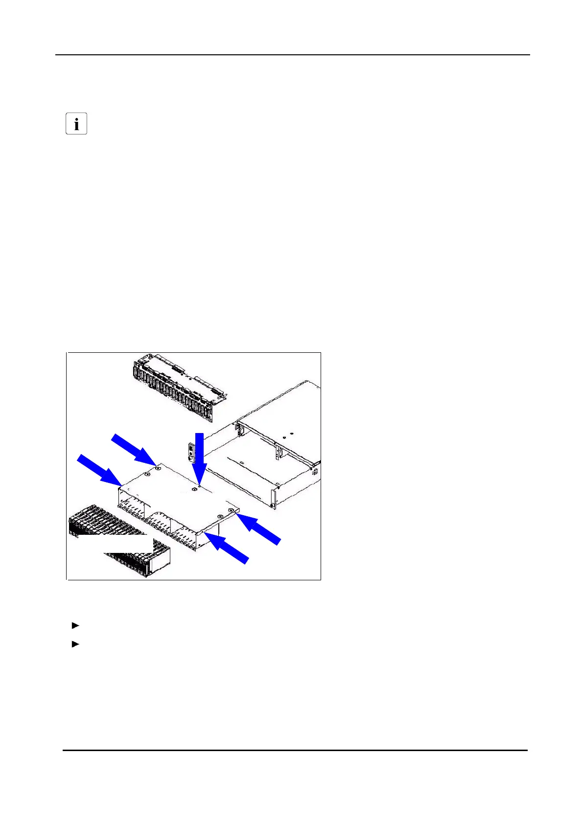
Figure 6: Screws securing the backplane case on the chassis
Remove the screws (flat-head Phillips screws) securing the backplane case.
Remove the backplane case and deposit it bottom up.
 Loading...