EasyManuals Logo

Cisco C9200L-48P-4G User Manual

Cisco C9200L-48P-4G
90 pages
To Next Page IconTo Next Page
To Previous Page IconTo Previous Page
Page #50 background imageLoading...
Page #50 background image
Step 4 Press the release latch at the right side of the power supply module inward and slide the power supply out.
Do not leave the power-supply slot open for more than 90 seconds while the switch is operating.
Caution
This unit might have more than one power supply connection. All connections must be removed to
de-energize the unit. Statement 1028
Warning
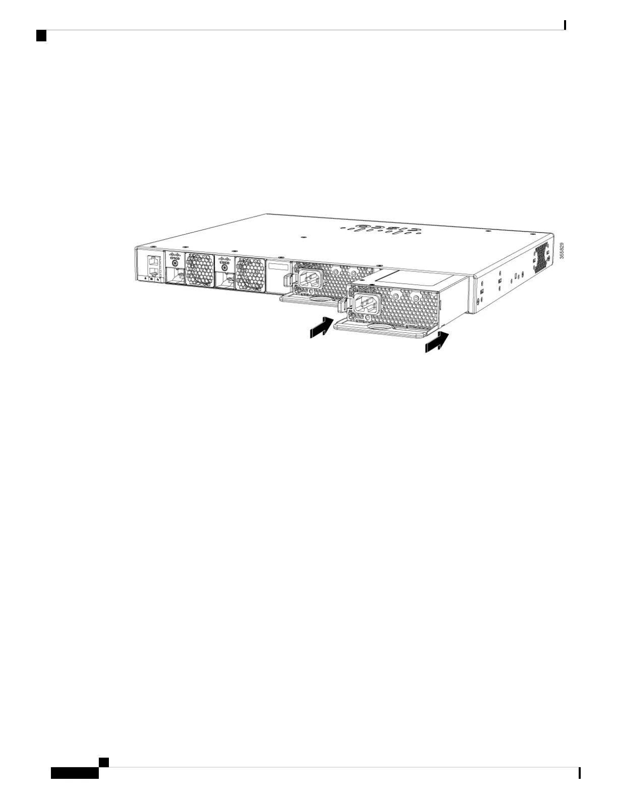
Step 5 Insert the new power supply into the power-supply slot, and gently push it into the slot. When correctly
inserted, the power supplies (excluding the power cord retainer) are flush with the switch rear panel.
Figure 29: Inserting the AC-Power Supply in the Switch
Step 6 (Optional) Install the power cord retainer as follows:
Cisco Catalyst 9200 Series Switches Hardware Installation Guide
44
Installing a Power Supply Unit
Installing or Replacing an AC Power Supply Module

Table of Contents

Questions and Answers:

Question and Answer IconNeed help?

Do you have a question about the Cisco C9200L-48P-4G and is the answer not in the manual?

Cisco C9200L-48P-4G Specifications

General IconGeneral
ModelC9200L-48P-4G
CategorySwitch
Uplink Interfaces4 x 1G SFP
Switching Capacity176 Gbps
PoE Budget740W
Stacking Bandwidth80 Gbps
Enclosure TypeRack-mountable - 1U
Power Over Ethernet (PoE)Yes
RAM2 GB
Flash Memory4 GB
Power DeviceInternal power supply
Voltage RequiredAC 120/230 V (50/60 Hz)
Ports48 x 10/100/1000 PoE+
MAC Address Table Size16K
Jumbo Frame SupportYes
Routing ProtocolRIP
Remote Management ProtocolSNMP
FeaturesQuality of Service (QoS), VLAN support, Access Control List (ACL) support, DHCP snooping, IPv6 support
Compliant StandardsIEEE 802.3, IEEE 802.3u, IEEE 802.3af, IEEE 802.3at
Operating Temperature0 to 40 °C
Operating Humidity10 to 90% non-condensing

Related product manuals