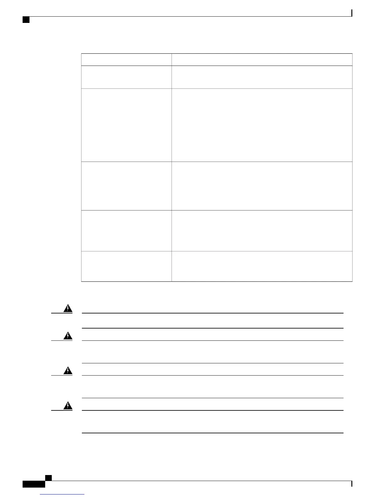
DescriptionTask
Construct and attach a system ground wire from the building (earth)
ground to the system ground point on the chassis.
Connecting the chassis to system
ground
Modules that you order with the chassis are installed on the chassis
when delivered. Blank faceplates are installed on empty module slots.
•
For the list of supported devices, see Supervisor Engine, on page
3 and Modules, on page 3.
•
For detailed installation instructions, see the Catalyst 6500 Series
Switch Supervisor Engine Guide and the Catalyst 6500 Ethernet
Module Installation Guide available on Cisco.com.
Installing the supervisor engine and
line cards and cabling them to the
network
PSMs that you order with the chassis are installed on the chassis when
delivered. Blank faceplates are installed on empty power supply module
slots.
For more information, see the chapter "Removing and Installing Power
Supplies, on page 50".
Installing power supplies
The fan tray that you order with the chassis is installed on the chassis
when delivered.
For more information, see the chapter "Removing and Installing the
Fan Tray, on page 54".
Installing the fan tray
After completing the network cabling and making sure that system
ground is connected, the power supplies can be turned on. The system
powers up and runs through a set of built-in diagnostics.
Powering up the chassis
These warnings apply to the overall switch installation process:
Class 1 laser product. Statement 1008Warning
This unit is intended for installation in restricted access areas. A restricted access area can be accessed
only through the use of a special tool, lock and key, or other means of security. Statement 1017
Warning
This unit might have more than one power supply connection. All connections must be removed to
de-energize the unit. Statement 1028
Warning
Only trained and qualified personnel should be allowed to install, replace, or service this equipment.
Statement 1030
Warning
Cisco Catalyst 6807-XL Switch Hardware Installation Guide
30 OL-30656-01
Installing the Switch
Installation Tasks

 Loading...


