Procedure
Step 1
Use a wire-stripping tool to remove approximately 0.75 inches (19 mm) of the covering from the end of the
grounding wire.
Step 2
Insert the stripped end of the grounding wire into the open end of the right-angled grounding lug.
Step 3
Crimp the grounding wire in the barrel of the grounding lug. Verify that the ground wire is securely attached
to the ground lug.
Step 4
Secure the grounding lug to the system ground connector with two M4 screws. Ensure that the grounding lug
and the grounding wire do not interfere with other switch hardware or rack equipment.
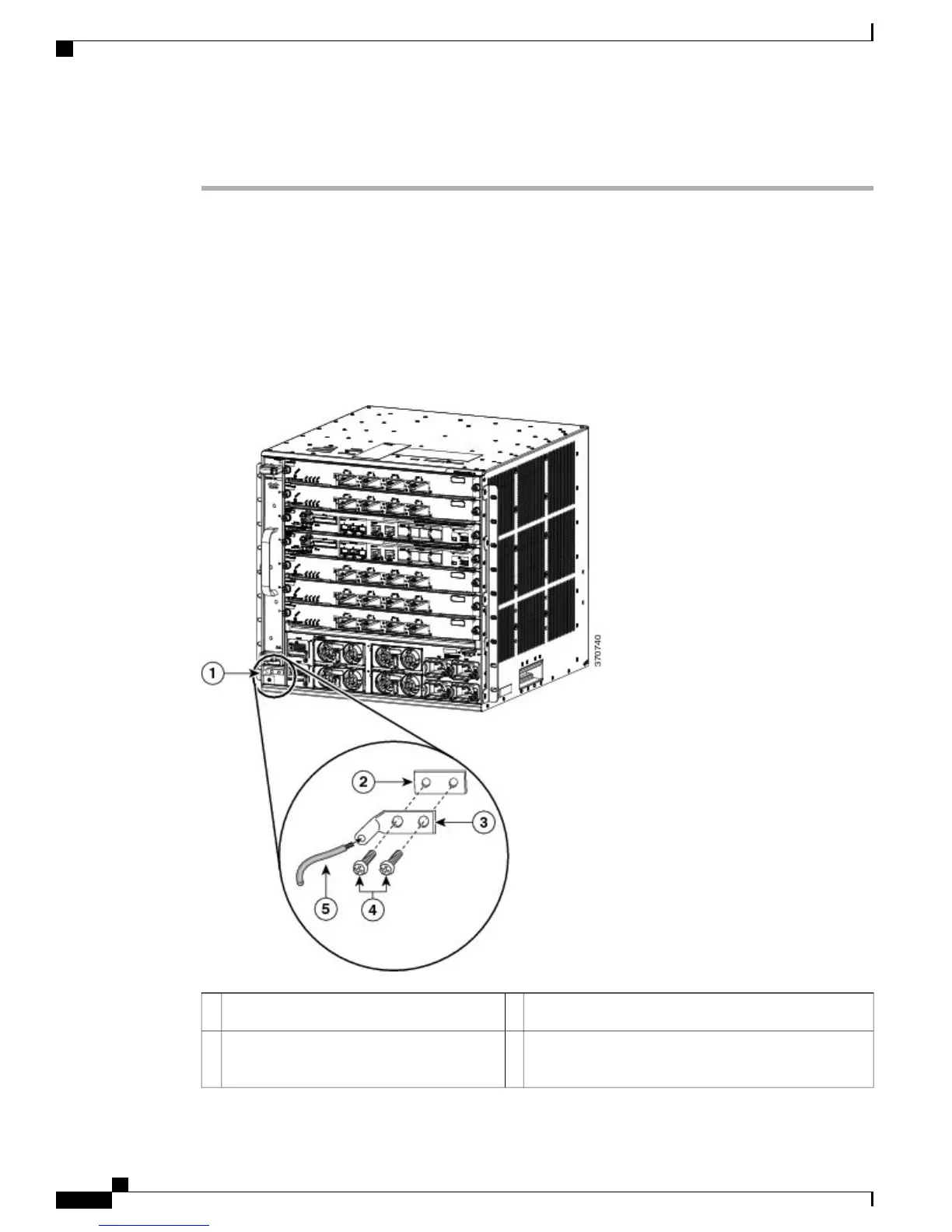
Figure 12: Locating and Connecting System Ground
M4 screws to secure the lug to the connector4System ground location1
Stripped end of the grounding wire inserted into the
open end of the right-angled grounding lug
5System ground connector2
Cisco Catalyst 6807-XL Switch Hardware Installation Guide
42 OL-30656-01
Installing the Switch
Establishing System Ground

 Loading...


