The slot inside the power supply bay ensures that PSM is installed in only one direction.Tip
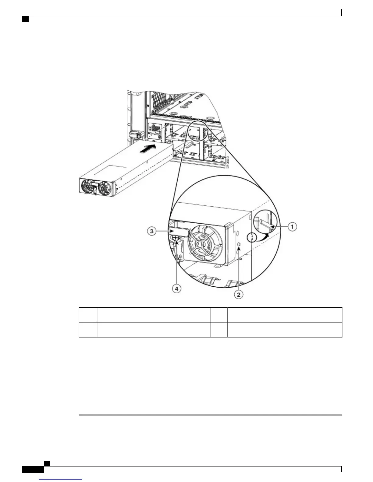
Figure 15: Installing the Power Supply Module
Latch3Slot in the power supply bay1
Captive installation screw4Nub on the PSM that slides into the slot2
Step 4
Rotate the latch up and tighten the captive installation screw to lock the latch in place.
Step 5
Plug the AC power cord (connected to a power source on one end) into the corresponding power entry module
(PEM). For example, if you have installed the PSM in bay 1, plug the power cord into AC1.
For a list of supported AC power cords for your particular AC input power supply, see 3000 W Power Supply
AC Power Cords, on page 67.
Step 6
Tighten the screw on the cable clamp next to the PEM. This ensures that the power cord is not accidentally
pulled out. See callout (5) in Figure 16: PSM and PEM, on page 53
Cisco Catalyst 6807-XL Switch Hardware Installation Guide
52 OL-30656-01
Removing and Replacing FRUs
Installing AC Power Supplies

 Loading...


