The Digital I/O Connector
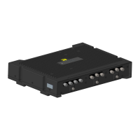
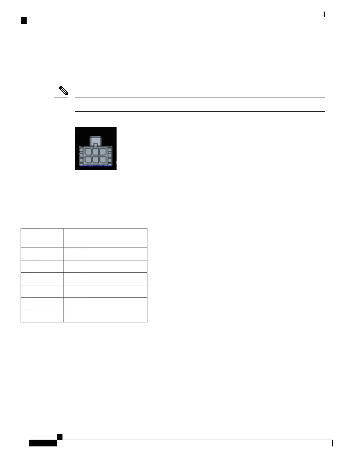
The following graphic shows the connector.
The default state of the Digital I/O is input, the open-collector is open (off).
Note
Figure 25: Digital I/O connector
The power connector pin-puts are as follows:
• Top Row - Pins 6, 5, 4
• Bottom Row - Pins 3, 2, 1
The pinouts for the Digital I/O are described in the following table.
Table 9: Digital I/O Pinouts
DescriptionDirectionNamePin
#
Digital IO Port 3I/ODIGI_IO_11
Ground-GND2
Digital IO Port 2I/ODIGI_IO_33
Digital IO Port 4I/ODIGI_IO_24
Ignition input (6V - 36V)InIgnition5
Digital IO Port 1I/ODIGI_IO_46
Vehicle Connections
When connecting to automotive power, it is expected that the ignition output will be +12 VDC, or +24 VDC
(following the battery voltage). Connect the Ignition Input (IGN) of the router to the ignition output of the
automobile. The DC In + and DC In - leads can be directly connected to the battery, but it is recommended
that they be connected after a fuse.
Cisco Catalyst IR1800 Rugged Series Router Hardware Installation Guide
60
Digital I/O, Ignition, and CAN Bus Connectivity
The Digital I/O Connector
 Loading...