• High speed CAN Bus 2.0B : ISO 11898-1 data link layer, ISO 11898-2 and ISO-11898-5 physical layer
up to 1Mbs data rate (SW dependent)
• Maximum Cable length between 500m (125 kbit/s) and 40m (1 Mbit/s)
• 120 ohms CAN bus termination
• There is no hardware mechanism to detect if an ODB II connector is attached
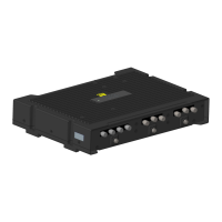
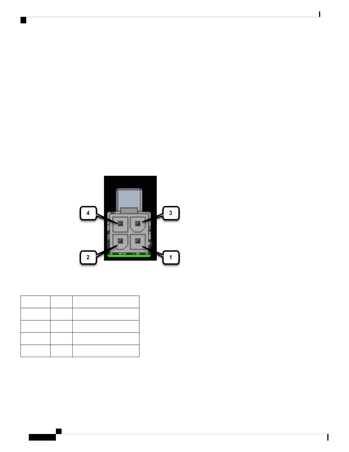
Can Bus Power Connector
The CAN_P and CAN_N signals are connected to 2 pins of the 4-pin Mini-fit power connector. A cable can
be connected from the Mini-fit connector to the OBD-II connector of the vehicle to get both unswitched power
and CAN interface input.
The pinouts are shown in the following:
Figure 26: Power Connector
Table 12: Power connector Descriptions
DescriptionNamePin Number
DC Power Return (GND-)DC -1
CAN bus Differential SignalCAN_P2
DC Power Input (12V, 24V)DC +3
CAN bus Differential SignalCAN_N4
On-Board Diagnostic (OBD-II)
The following are some of the characteristics of On-Board Diagnostic (OBD-II)
Cisco Catalyst IR1800 Rugged Series Router Hardware Installation Guide
62
Digital I/O, Ignition, and CAN Bus Connectivity
Can Bus Power Connector
 Loading...