Rear Panel Layout
This section details the rear panel layout, LEDs and ports.
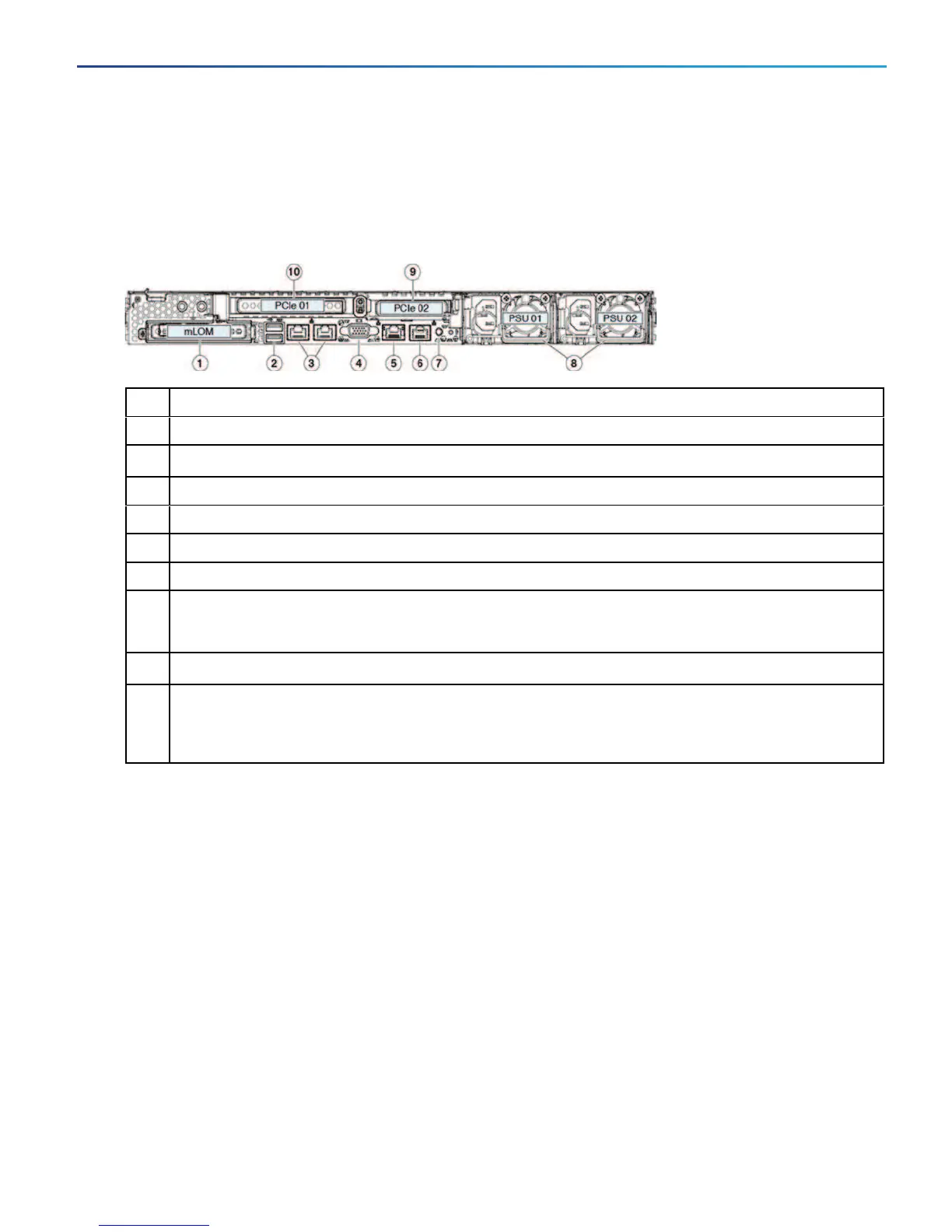
Figure 2 Rear view of the Cisco Expressway
1 Modular LAN on Motherboard (mLOM) card slot (not populated)
2 USB 3.0 ports (two slots)
3 LAN3 and LAN4 (do not use)
4 VGA video connector
5 CIMC/dedicated management port (1 Gb Ethernet)
6 Serial port (RJ-45 connector)
7 Rear identification button/LED
8
Power supplies PSU 01 and PSU 02
The second power supply can be added for 1+1 redundancy
9
Slot 2: Low-profile PCIe slot on riser (not populated)
10
Slot 1: Standard-profile PCIe slot on riser; houses two SFP ports
Left port is LAN1 (NIC1) in the Expressway user interface
Right port is LAN2 (NIC2) if used in the interface
9
Cisco Expressway CE1200 Appliance Installation Guide
Rear Panel Layout
 Loading...