Table 9: GNSS Technology Support
SupportReceive (Rx) Band MHzRF BandTechnology
Supported1575.42 +/- 1.023GPSGNSS
Not
Supported
1597.52 - 1605.92GLONASS
Not
Supported
1575.42 +/- 2.046Galileo
Not
Supported
1561.098 +/- 2.046BeiDou
Power Supply
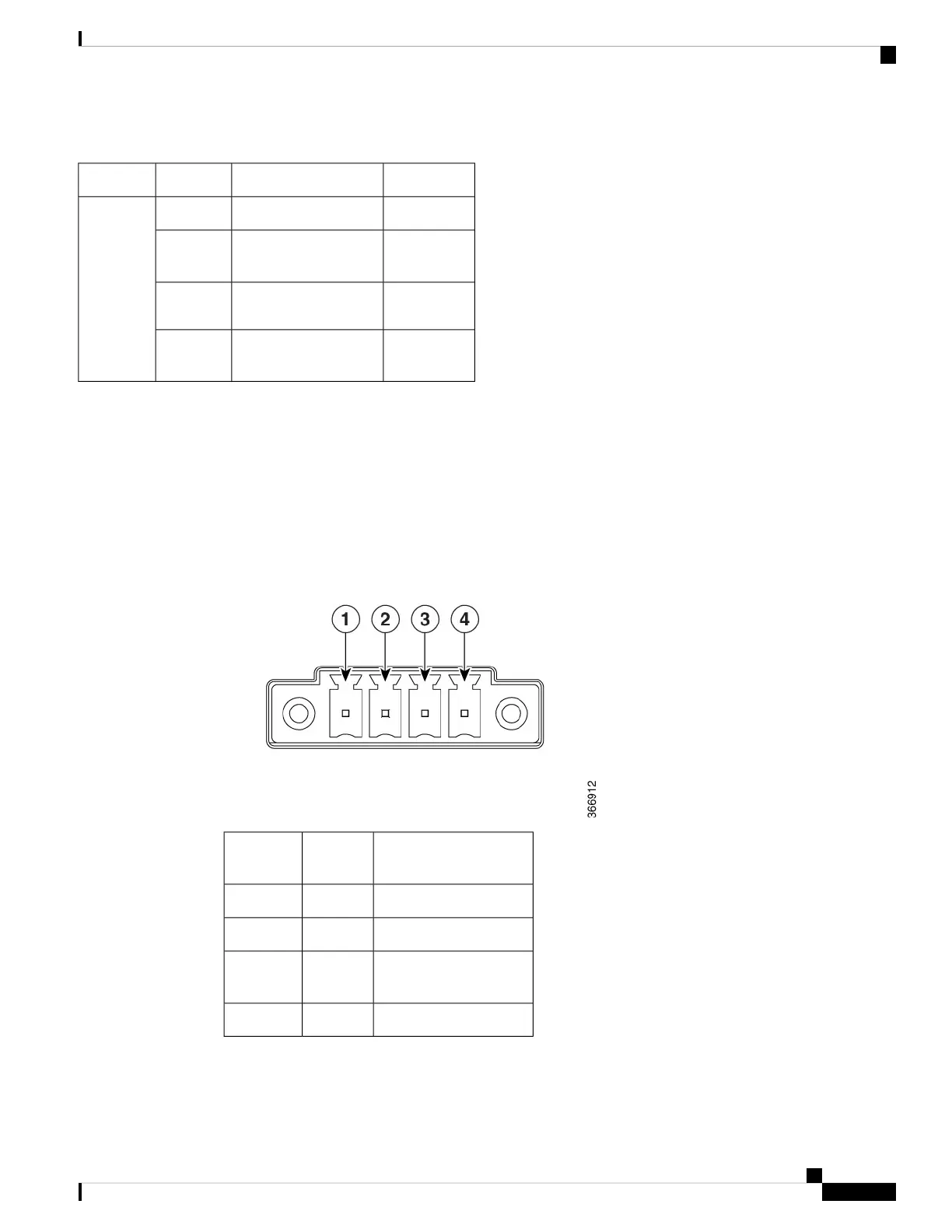
The Cisco IR1101 comes with an external DC power connector. The 4-pin power entry connector (receptacle)
is mounted to the unit. The 4-pin power entry mating connector (plug) is attached to the receptacle. It is
removed during installation and used to connect to the DC power source, then reattached to provide power
to the unit.
Refer to Figure 11 for the location and values of the power connector.
Figure 12: Power Connector Pin-Outs
DescriptionNamePin
Number
DC Power Positive InputDC In +1
DC Power ReturnDC In -2
Alarm CommonALM
REF
3
Alarm InputALM IN4
Product Overview
17
Product Overview
Power Supply
 Loading...