4-2
Cisco Nexus 5600 Series Hardware Installation Guide
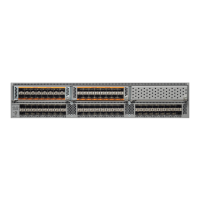
Chapter 4 Replacing Components
Replacing or Installing Power Supplies
Step 3 Open the packing materials for the module and prepare an antistatic surface for uninstalled modules.
Step 4 Loosen the captive screw on the ejector lever so that the lever can move.
Step 5 Rotate the ejector lever fully from the front of the module until it stops at about 80 degrees from the front.
Step 6 With one hand on the ejector handle and front of the module, pull the module part way out of its slot in
the chassis.
Step 7 Place your other hand under the module to support its weight and fully remove the module.
Step 8 Place the module on an antistatic surface or pack it in its packing materials.
You are ready to install a replacement module in the chassis as described in the “Installing an Expansion
Module in a Cisco Nexus 5600 Platform Chassis” section on page 4-2.
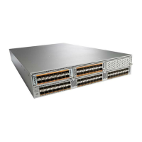
Installing an Expansion Module in a Cisco Nexus 5600 Platform Chassis
To install an expansion module in a Cisco Nexus 5600 Platform switch chassis, follow these steps:
Step 1 Remove the module from its packing materials and place it on an antistatic surface.
Step 2 Rotate the ejector lever away from the front of the module until it stops at about 80 degrees from the
front.
Step 3 Holding the module with one hand on the front of the module and the other hand on its carrier edges or
bottom, align the module to the open slot.
Step 4 Push the module fully into the slot until the ejector engages and the lever moves.
Step 5 Rotate the ejector lever to the front of the module so that the module is fully inserted in the slot and the
captive screw on the ejector assembly is in position to screw into the chassis.
Step 6 Tighten the captive screw on the expansion module to the chassis.
Step 7 Verify the installation by making sure that the module status LED turns on and is green.
Replacing or Installing Power Supplies
The Cisco Nexus 5600 series supports redundant power supplies. You must fill any unused power supply
slots with a blank covers to maintain the designed airflow.
If you need to replace an existing power supply, follow the procedures that explain how to remove and
install power supplies. If you are installing a new power supply where one did not exist before, follow
the installation procedure.
Note The airflow direction must be the same for all power supply and fan modules in the chassis. You can
order all modules with front to back airflow or back to front airflow. To change the airflow direction of
the chassis, you must power down the switch before swapping out all fan and power supply modules.
This section includes the following topics:
• Removing a Power Supply, page 4-3
 Loading...