Send documentation comments to nexus6kdocs@cisco.com.
2-14
Cisco Nexus 6000 Series Hardware Installation Guide
OL-15902-01
Chapter 2 Installing the Cisco Nexus 6000 Series Switches
Installing A Reverse Airflow System for Norcal-96
Installing A Reverse Airflow System for Norcal-96
In a standard airflow configuration, cold air intake is from the fan side and hot air exhaust is from the
port side. In a reverse airflow configuration, the cold air intake is from the port side and hot air exhaust
is from the fan side. A reverse air flow system must have new reverse air flow fans (four sets), new
reverse power supplies, and four reconfigured fan louvers.
A reverse airflow power supply is identified by a black colored stripe. A standard airflow power supply
does not have a black colored stripe.
A reverse airflow fan tray (N6K-C6004-FAN-B) is identified by a black colored label near the STAT
button. A standard airflow fan tray (N6K-C6004-FAN-F) is identified by a grey colored label near the
status LED.
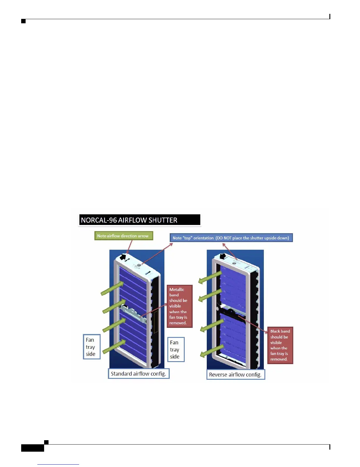
A reverse airflow configuration for an airflow shutter or fan louver ( part number 800-38434-03), is
identified by a black band that is visible when the fan tray is removed. It also has direction arrows
engraved on the top side that should point towards the fan trays. A standard airflow configuration for a
fan louver ( part number 800-38434-03), is identified by a metallic band that is visible when the fan tray
is removed. In this configuration the direction arrows on the top side should point towards the port side.
A standard airflow configuration and reverse airflow configuration for louvres are shown in Figure 2-2.
Figure 2-2 Standard airflow configuration and reverse airflow configuration for louvres