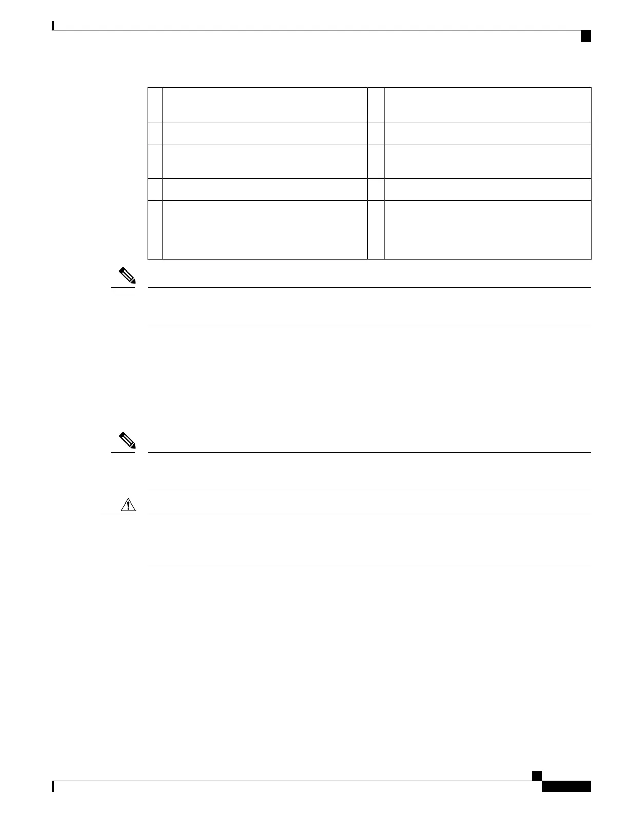
Three fan modules with fan slot 1 on the left and
fan slot 3 on the right
6Out-of-band management port (SFP port)1
Chassis LEDs (Beacon [BCN] and Status [STS])7Console port (RS232 port)2
Screw holes (6) for attaching rack mounting
brackets
8Out-of-band management port (RJ-45 port)3
Screw holes (2) for attaching grounding lug.9USB port used for saving or copying functions4
Two power supplies (one used for operations and
one used for redundancy) (AC power supplies
shown) with power supply slot 1 on the left and
slot 2 on the right
5
USB support is limited to USB 2.0 devices that use less than 2.5 W (less than 0.5 A inclusive of surge current).
Devices, such as external hard drives, that instantaneously draw more than 0.5 A are not supported.
Note
Depending on whether you plan to position the ports in a hot or cold aisle, you can order the fan and power
supply modules with port-side intake (burgundy colored) or port-side exhaust (blue colored) airflow. All of
the power supply and fan modules must have the same coloring.
The fan and power supply modules are field replaceable and you can replace one fan module or one power
supply module during operations so long as the other modules are installed and operating. If you have only
one power supply installed, you can install the replacement power supply in the open slot before removing
the original power supply.
All of the fan and power supply modules must have the same direction of airflow. Otherwise, the switch can
overheat and shut down.
Note
If the switch has port-side intake airflow (burgundy coloring for fan modules), you must locate the ports in
the cold aisle. If the switch has port-side exhaust airflow (blue coloring for fan modules), you must locate the
ports in the hot aisle. If you locate the air intake in a hot aisle, the switch can overheat and shut down.
Caution
Cisco Nexus 9336C-FX2 NX-OS Mode Switch Hardware Installation Guide
3
Overview
Overview
 Loading...