10
Unpacking and Installing the Cisco ONS 15454 Four-Shelf and Zero-Shelf Bay Assembly
78-13271-05
Installation Instructions
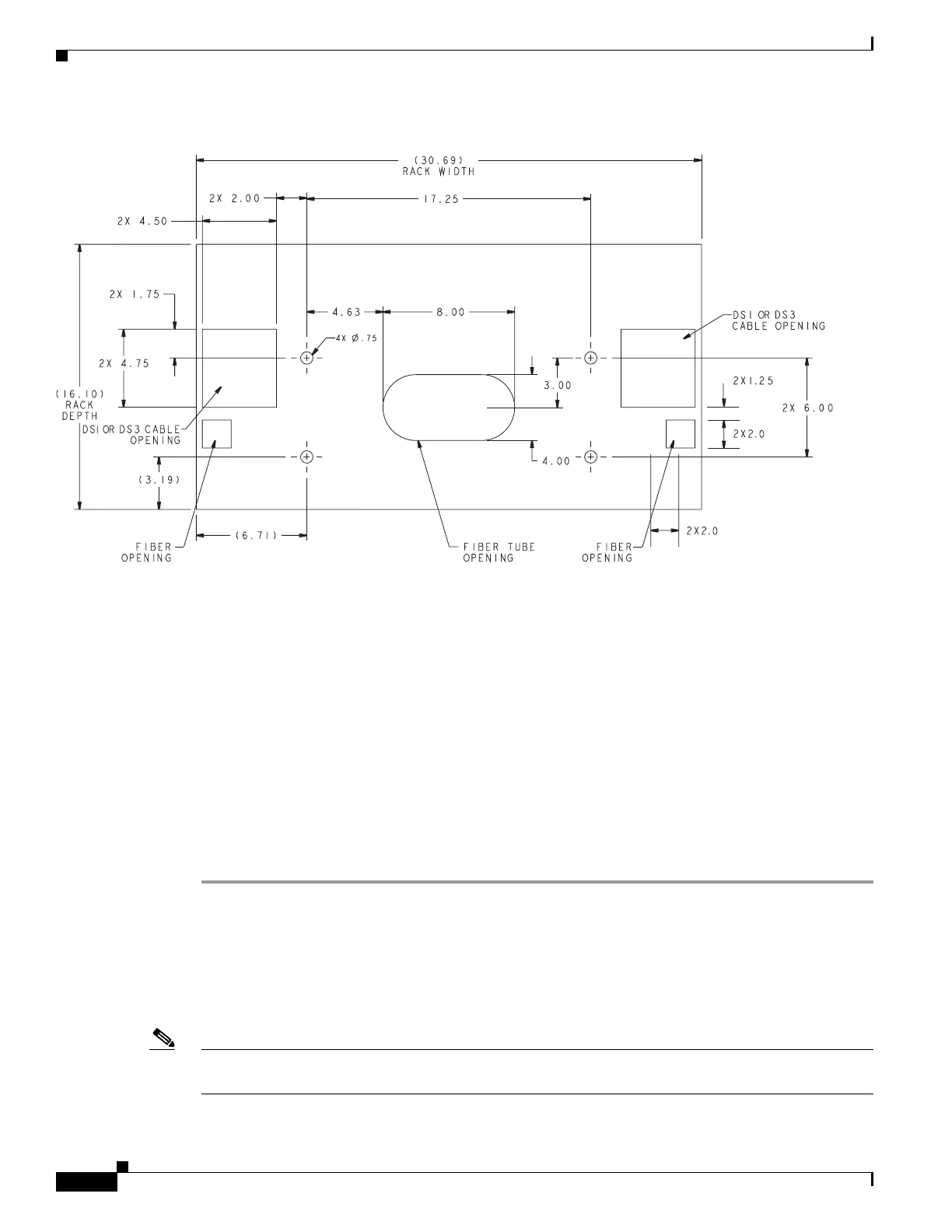
Figure 6 Raised floor cutout for CORE and local
Framework Anchoring
To anchor framework to a raised floor, you must know in what earthquake zone the equipment is being
installed. Zones 0–2A have the frames bolted to the raised floor through a u-channel across the bottom
of the floor tile and stringers. Zones 2B–4 have 1/2-inch threaded rods extending through the raised floor
and connected to seismic anchors with coupling nuts. In all zones, standard hold-down parts are used on
top of the floor with threaded rods of varying lengths. Anchors and hold-down material must be
engineered for proper seismic zone.
Seismic Zones 0–2A
To fasten network and unequal flange duct framework to a raised floor:
Step 1 Place a 1 5/8 x 1 5/8 u-channel (with continuous slot down) under the stringers and use clips to cover
the free ends of the u-channel where the threaded rod goes through to prevent it from spreading when
compressed.
In the base of the frame, use the hold-down plate engineered for that frame, threaded rod, nut, washer,
insulating bushing, and hold-down washer.
On the bottom of the u-channel, use the clip, washer, lockwasher, and nut.
Note The u-channel should not extend more than four inches past the edge of the stringers or it will block
access under the floor.
61254

 Loading...


