31
Unpacking and Installing the Cisco ONS 15454 Four-Shelf and Zero-Shelf Bay Assembly
78-13271-05
Install the Power and Ground
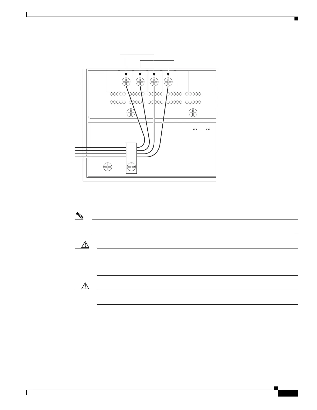
Figure 29 ONS 15454 power terminals
Step 4
Remove or loosen the #8 power terminal screws on the ONS 15454. To avoid confusion, label the cables
connected to the BAT1/RET1 (A) power terminals as 1, and the cables connected to the BAT2/RET2 (B)
power terminals as 2.
Note Use only pressure terminal connectors, such as ring types, when terminating the battery, battery
return, and frame ground conductors.
Caution Before you make any crimp connections, coat all bare conductors (battery, battery return, and
frame ground) with an appropriate antioxidant compound. You do not need to prepare tinned,
solder plated, or silver-plated connectors and other plated connection surfaces, but always
keep them clean and free of contaminants.
Caution When terminating power, return, and frame ground, do not use soldering lug, screwless
(push-in) connectors, quick-connect, or other friction-fit connectors.
Step 5 Strip 1/2 inch of insulation from all power cables that you will use.
Step 6 Crimp the lugs onto the ends of all power leads.
67464
RET 1
CAUTION: Remove power from both
the BAT1 and BAT2 terminal blocks
prior to servicing
SUITABLE FOR MOUNTING ON
A NON-COMBUSTIBLE SURFACE.
PLEASE REFER TO INSTALLATION
INSTRUCTIONS.
-48 V 24 A
BAT 1 RET 2 BAT 2
Battery leads (red)
Return leads (black)

 Loading...


