DIMMs and Channels
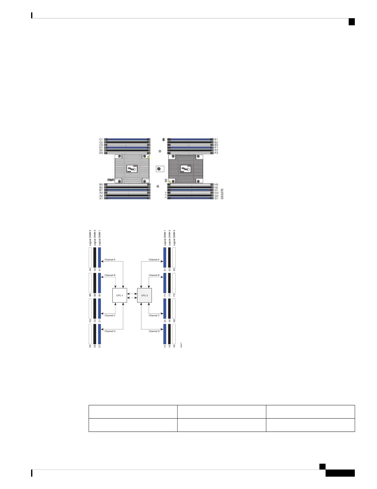
Each channel is identified by a letter—A, B, C, D for CPU 1, and E, F, G, H for CPU 2. Each DIMM slot is
numbered 1, 2, or 3. Note that each DIMM slot 1 is blue, each slot 2 is black, and each slot 3 is off-white or
beige.
The figure below shows how DIMMs and channels are physically laid out on the blade server. The DIMM
slots in the upper and lower right are associated with the second CPU (CPU shown on right in the diagram),
while the DIMM slots in the upper and lower left are associated with the first CPU (CPU shown on left).
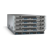
Figure 13: Physical Representation of DIMMs and Channels
The figure below shows a logical view of the DIMMs and channels.
Figure 14: Logical Representation of DIMMs and Channels
DIMMs can be used in the blade server in a one DIMM per Channel (1DPC) configuration, in a two DIMMs
per Channel (2DPC) configuration, or a three DIMMs per Channel (3DPC) configuration.
The following tables show recommended DIMM population order for non-mirroring and mirroring
configurations. For single-CPU configurations, read only the CPU 1 columns of the tables.
Table 1: Supported DIMM Population Order (Non-Mirroring)
CPU 2 Installed SlotsCPU 1 Installed SlotsDIMMs Per CPU
E1A11
Servicing a Blade Server
15
Servicing a Blade Server
DIMMs and Channels

 Loading...