3-4
Cisco UCS S3260 Storage Server Chassis Installation and Service Guide
Chapter 3 Maintaining the System
Status LEDs and Buttons
Rear-Panel LEDs and Buttons
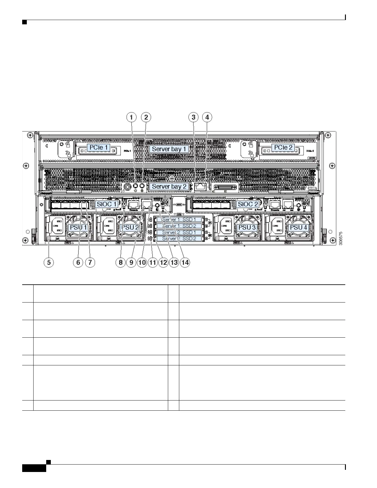
Figure 3-2 shows the rear-panel LEDs and buttons for a S3260 system. This example is shown with a
C3X60 M4 server node and an optional four-drive expansion module. Table 3-2 defines the rear-panel
LED states.
Figure 3-2 S3260 System Rear-Panel LEDs and Buttons
1 Server node Power button/LED
(on each server node)
8 Not used at this time.
2 Server node unit identification button/LED
(on each server node)
9 10/100/1000 dedicated management port link activity LED
(on each SIOC)
3 1 Gb Ethernet port link speed LED
(on each M5 server node only)
10 10/100/1000 dedicated management port link speed LED
(on each SIOC)
4 1 Gb Ethernet port link activity LED
(on each M5 server node only)
11 Solid state drive activity LED (each drive bay)
5 Power supply status LED (each power supply) 12 Solid state drive fault LED (each drive bay)
6 QSFP port link speed LED (on each port)
Actual ports will vary, depending on which SIOC
version is used, or which adapter card is installed
in a Version 03 SIOC.
13 Not used at this time.
7 QSFP port link activity LED (on each port) 14 SIOC health LED (one each Version 03 SIOC only)
 Loading...


