to be used with an external UPS system, and it has status signals that are reported to Cisco VG310 or Cisco
VG320.
The following table shows the connector pin assignment for the +12V DC power connector pin assignment.
Table 3: +12V DC Connector Pin Assignment
DefinitionSW Register
0x4A80_0038
DescriptionDirectionPin
——Enable (tie low)Input1
——+12V (power)Input2
Battery Missing:
Fail 1 = missing
Fail 0 = good
Bit 6:
REP_MIS_BAT
REP_BAT (tie low)Output3
——GND (power
return)
Input4
Battery on/off:
Status 1 = off
Status 0 = on
Bit 4: BAT_ONON_BAT (tie low)Output5
——+12V (power)Input6
Battery power:
Level status 1 = low
Level status 0 = okay
Bit 5: BAT_LOWLOW_BAT (tie
low)
Output7
——GND (power
return)
Input8
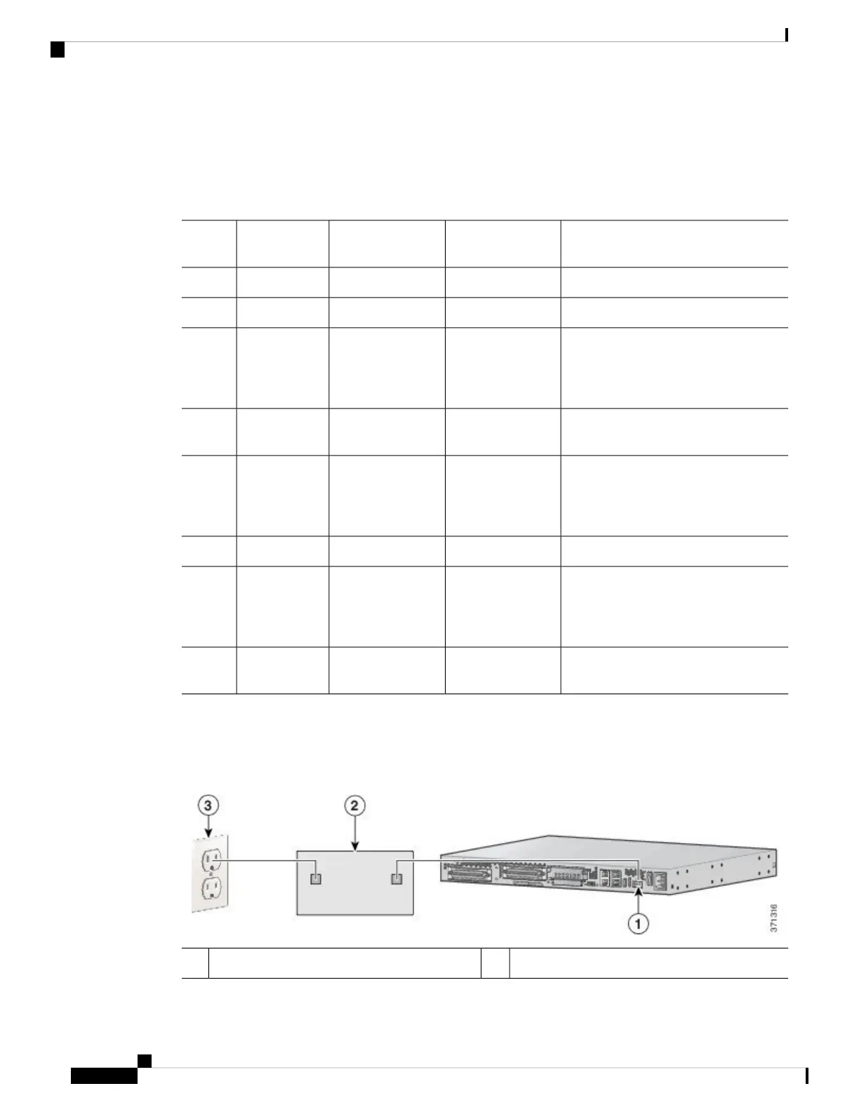
Connecting a Battery to a DC-Powered Chassis
The following figure shows a setup that uses an external battery. This is one of the many possible setups.
Figure 9: Connecting a Battery to a DC-Powered Chassis
AC wall plug3DC plug1
Installing the Cisco VG310 and Cisco VG320 Voice Gateways
16
Installing the Cisco VG310 and Cisco VG320 Voice Gateways
Connecting the Chassis to a +12V DC Power Supply