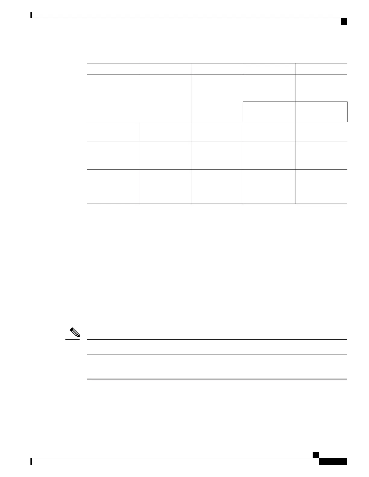
Table 6: Reference Guidelines for Cable Usage
Pinout InformationInterface ToConnector/CablePort ColorVoice Gateway Port
Console and
Auxiliary Port
Signals and Pinouts
PCRJ-45/RolloverLight blueConsole
Console Port to
ASCII Terminal
ASCII terminal
Auxiliary Port
Signals and Pinouts
ModemRJ-45/Rollover
BlackAuxiliary
Gigabit Ethernet
Connector Pinouts
(RJ-45)
LANRJ-45/Gigabit
Ethernet
YellowGigabit Ethernet
Analog Voice RJ-21
Pinouts
Distribution panel
for analog
telephone, fax, PBX,
or central office line
RJ-21X/
50-conductor
GrayAnalog voice
multiport
Remote Terminal Connections (If Applicable)
If you are configuring a voice gateway from a remote location, connect the modem and the remote PC or
terminal to the telephone network as described in this section.
Connecting to a Modem
To connect the local modem and the remote modem to live telephone outlets, use standard telephone cables.
Connecting to a Remote PC
Before you begin
The remote PC must be running terminal emulation software.
Note
Procedure
Step 1 Connect the remote PC to the modem.
Step 2 Set the PC terminal emulation software requirements as follows:
• 9600 baud
• 8 data bits
Installing the Cisco VG310 and Cisco VG320 Voice Gateways
23
Installing the Cisco VG310 and Cisco VG320 Voice Gateways
Remote Terminal Connections (If Applicable)