Battery2
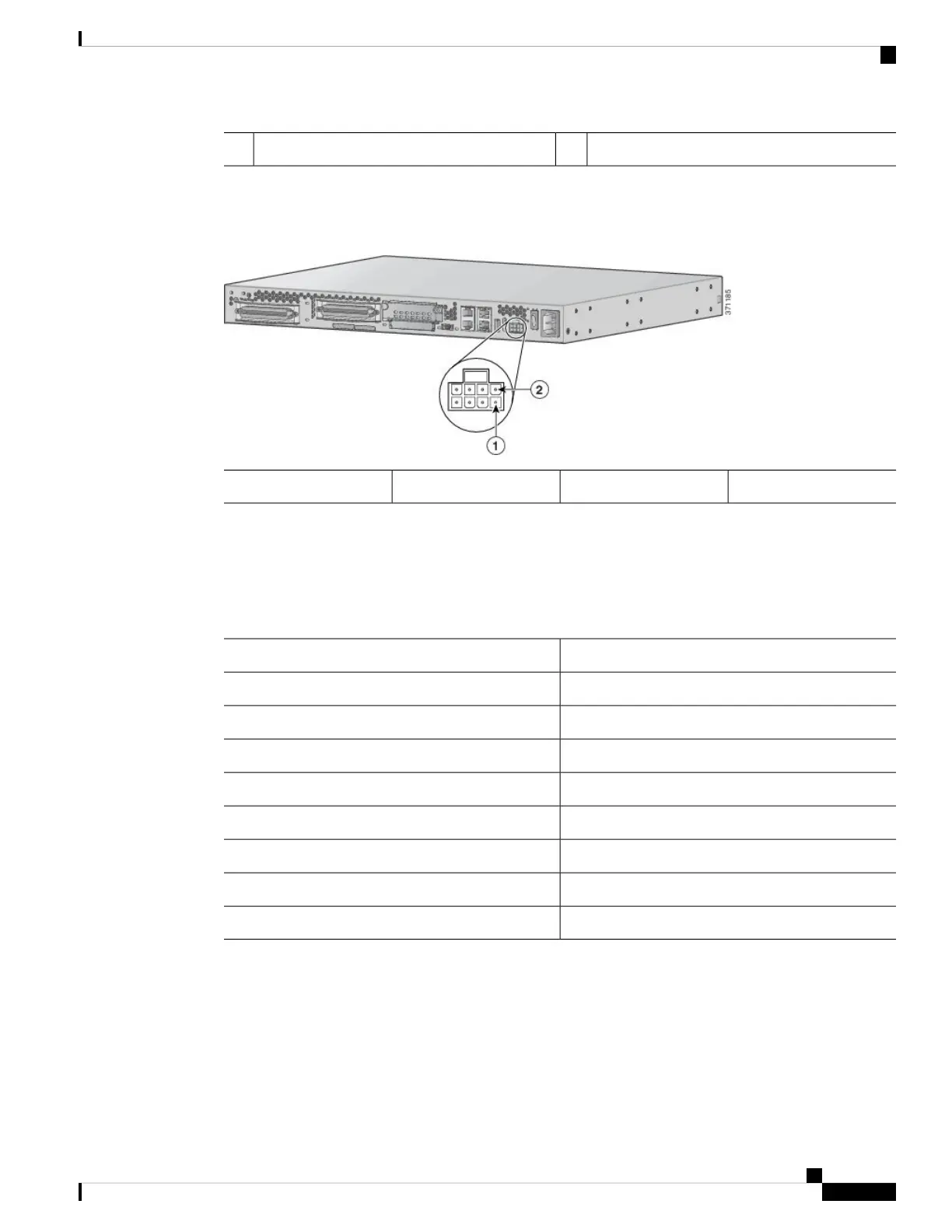
Connect the battery to the DC input connector on your Cisco VG310 or Cisco VG320. The following figure
shows the DC power connector.
Figure 10: +12V DC Power Connector
Pin 52Pin 11
Pinouts for the DC Power Connector
The following table provides information about the pinouts for the DC power connector on Cisco VG310 and
Cisco VG320.
Table 4: Pinouts for the DC Power Connector
DescriptionPin Number
GND (input enable)1
+12V (power)2
REP_BAT (replace battery)3
GND (power return)4
ON_BAT (battery is on)5
+12V (power)6
LOW_BAT (battery is low)7
GND (power return)8
Connecting to a Console Terminal or Modem
The Cisco VG310 or Cisco VG320 analog voice gateway unit has an asynchronous serial port and an auxiliary
port. These ports provide administrative access to the unit either locally (with a console terminal or a PC) or
remotely (with a modem). To configure the unit using the Cisco IOS CLI, you must establish a connection
between the console port on the voice gateway and either a terminal or a PC.
Installing the Cisco VG310 and Cisco VG320 Voice Gateways
17
Installing the Cisco VG310 and Cisco VG320 Voice Gateways
Connecting to a Console Terminal or Modem