4. Interface specifications
4.1 Input buffer
Buffer size: 4K bytes
4.2 Serial interface
(Bold letters signify the default setting)
Interface: 2-way serial communication
Signal level: RS-232C
Baud rate: 1200, 2400, 4800, 9600, 19200, 38400, 57600, 115200 bps (switch via command)
Data length: 7 or 8 bit
Start bit: 1 bit
Stop bit: Greater than 1 bit
Parity: None, even number, odd number
Flow control: DTR/DSR, Xon/Xoff
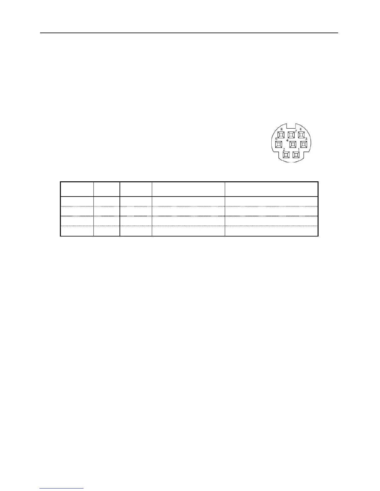
Connector: Printer side mini-DIN 8-pin female connector
PC side (dedicated cable) D-SUB 9-pin
Connector pin arrangement
1 RXD Input Receives data
Number 3 pin (RXD)
2 TXD Output Sends data
Number 2 pin (TXD)
3 DTR Output Printer busy signal
Number 6 & 8 pins (DSR, CTS)
5 GND
-
Ground
Number 5 pin (GND)
[Terminal name explanations]
・TXD (Transmit Data)
Line for sending serial data from the printer to the host
When there is data flow control via x-ON/x-OFF: If the buffer reaches 8000 bytes
remaining while receiving data then DC3 (13H: Data receive disable signal) is output.
If the buffer reaches 8192 bytes remaining while receiving data then DC1 (11H: Data
receive enable signal) is output.
・RXD (Receive Data)
Line for sending serial data from the host to the printer. Framing error, overrun
When an error occurs the characters are distorted.
・DTR (Data Terminal Ready)
This is enabled when DTR/DSR flow control is selected.
When this signal is ready, data and commands can be written to the input buffer.
When this signal is busy, writing data causes an overrun error and the data is ignored.
The input buffer can be written to while printing. Busy may occur during self printing
when the power is turned on.
・GND (Signal Ground)
Signal line GND
 Loading...