a
OPERATION N’ MA. 410-O : (./~rrkiq N,,I/ </r/jes/irq /hc /mvI n.v/<. /(vi/.
VI. CHECKING AND ADJUSTING THE STEERING GEOMETRY
The
crossmember
supporting the steering has slots at its fixing point on the front subframe.
Any vertical movement of this crossmember alters the steering geometry.
WARNING
This operation is only to
be
carried out in certain ccxses such as
-accidental impact, with repercussions on the steering system.
-work on the vehicle entoiling removal of steering crossmember.
- vehicle with poor
road
stability ( p
oar stright-line stability) 01
with excessive tyre weor.
CHECKING
1,
Prepare the vehicle. as for checking front wheel
alignment ( Srr ~ho/,lvr
V I.
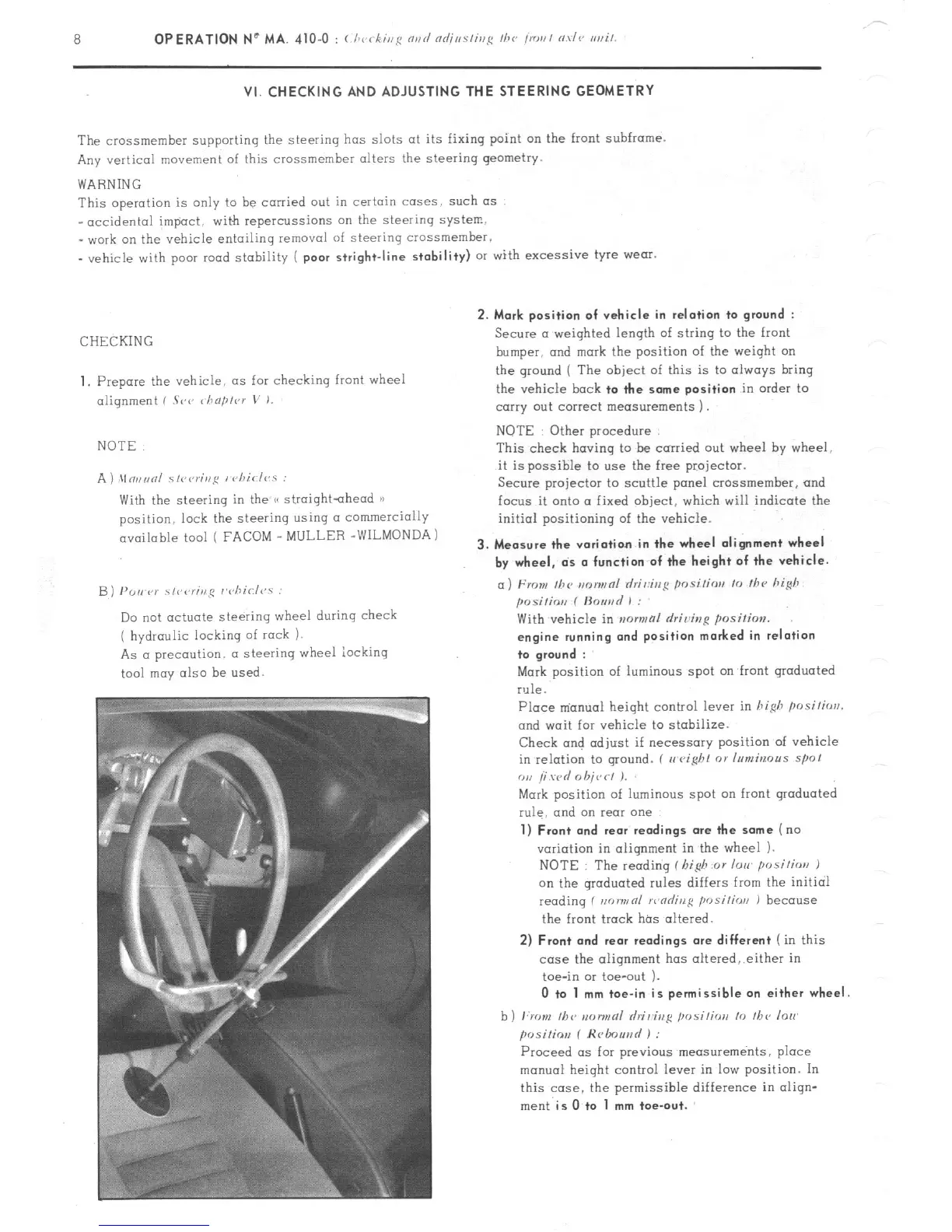
NOTE
A ) \In,,unl ~fi~<,r;,,~ I chiclvs :
With the steering in the /< straightahead 1)
position. lock the steering using CI commercially
available tool ( FACOM _ MULLER -WILMONDA)
B) PO,, P)’ \,r,rr;ng r’cliirl<,.s :
Do not actuate steering wheel during check
( hydraulic locking of rock 1.
As a precaution. a steering wheel iocking
tool may also be
used.
2. Mark position of vehicle in relation to
ground :
Secure a weighted length of string to the front
bumper. and
mark
the position of the weiqht on
the ground ( The
object
of this is to always bring
the vehicle
bock to the some position
in order to
carry out correct measurements 1.
NOTE Other procedure
This check having to be carried out wheel hy wheel.
it is possible to use the free projector.
Secure projector to scuttle panel crossmemher, and
focus it onto a fixed object, which will indicate the
initial positioning of the vehicle.
3. Measure the variation in the wheel alignment wheel
by wheel, ds o function of the height of the vehicle.
a) From Ihc m~nwnl rlri,:ir,g posi/ior, lo /hc hi@
posilio,, f ftouad 1 :
With vehicle in mwmal rlriving
position.
engine running ond position marked in relation
to groond :
Mark position of luminous spot on front graduated
rule.
Place m’anual height control lever in hi&
posilirrrl.
and wait for vehicle to stabilize.
Check and adjust if necessary position of vehicle
in relation to ground. ( II
eight 01 Inmbrous spol
ou /i wd 0 hit,< I J.
Mark position of luminous spot on front graduated
rule. and on rear one
1) Front and rear
readings ore the some (no
variation in alignment in the wheel 1.
NOTE : The reading f I,i$ or lorr posilios J
on the qroduated rules differs from the initial
reading f non,,nl >r,nrlinl:
position J
because
the front track has altered.
2) Front and rear readings ore different
( in this
case the alignment has oltered,.either in
toe-in or toe-out ).
0 to 1 mm toe-in is permissible on either wheel
b) ,:rr ,,I, /bv IIDIINRI hi&g ,,osi,;orr lo ,I,<, lo,,
posiliov f Hrlmuad ) :
Proceed OS for previous measurements, place
manual height control lever in low position. In
this case. the permissible difference in oliqn-
ment
is
O.to
1 mm toe-out.