OPERATION No MA. 4104 : (./ ,
k’
1<c a,,g I,< n / nd;i,,s/i,,g I/><, jr.or,/ ovl<, ,,i,it
Op. MA’. 410-O 9
ADJUSTMENT
NOTE The steering crossmember will have to be
moved (IS a function of the readings obtained during
checkinq
01) Towards the
top to
obtain
_ toe-out ir, Ihe hish positim
- toe-in irr the 10~ psitios
b) Towards the
bottom
to obtain
.
toe-in
in Ihr hi& posilins
- toe-out iu fhc IOU posilios
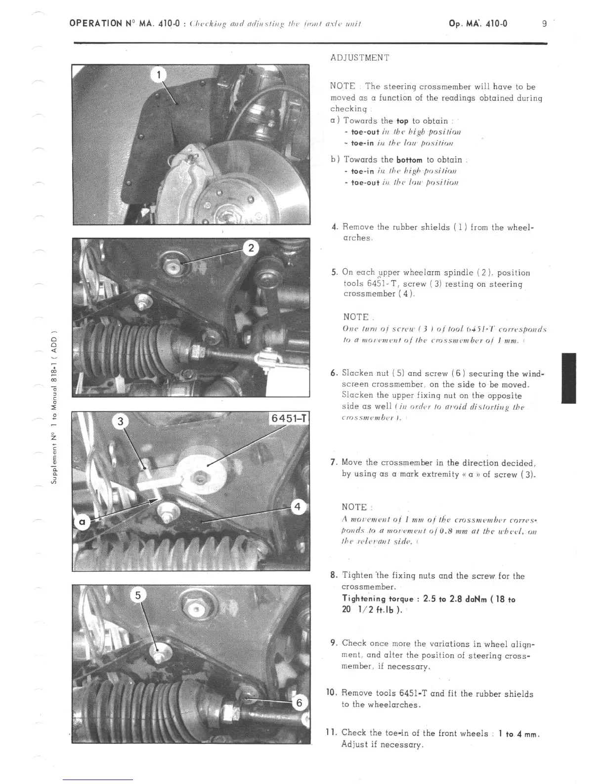
4. Remove the rubber shields ( 1 ) from the wheel-
arches.
5. On each ,upper wheelorm spindle (2 ). position
tools 6451-T, screw (3) resting on steering
crossmember ( 4 1.
NOTE.
6. Slacken nut ( 5) and screw (6 1 securing the wind-
screen crossmember. on the side to be moved.
Slacken the upper fixing nut on the opposite
side as well li,r order 10 nrmoid rlistorfina II><,
crr~.ss,nP”,b<~r ,,
7. Move the crossmember in the direct& decided,
by using (1s a mark extremity (( a u of screw ( 3).
8. Tighten ‘the fixing nuts and the screw for the
crossmember.
Tightening torque : 2.5 ta 2.8 doNm ( 18 ta
20 l/2 ft.lb ).
9. Check once mew the variations in wheel aliqn-
merit. and alter the position of steering cross-
member. if necessary.
10.
Remove tools 6451-T and fit the rubber shields
to the wheelarches.
Adjust if necessary.
11.
Check the toe-in of the front wheels
1 to 4 mm.