4
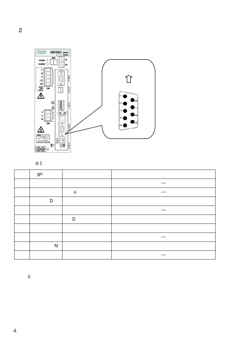
2.2 Communication Connector
The pin layout of PROFIBUS-DP communication connector CN3 is
shown below.
Pin layout of CN3 (D-sub 9pin)
We recommend the use of cables and connectors dedicated for PROFIBUS-DP. Also, a
terminal resistor is required when placing this product on the terminal of a network. Please
use a connector with a terminal resistor.
Connector (Example): SUBCON-PLUS-PROFIB/SC2 (Phoenix Contact)
Pin
Signal name
Function Description
1 Not used
―
2 Not used
―
3 RxD/TxD-P
Send/receive data Connect line B (red)
4 Not used
―
5 DGND GND GND for VP(bus terminal)
6 VP +5V power For bus terminal
7 Not used
―
8 RxD/TxD-N
Send/receive data Connect line A (green)
9 Not used
―
Up
 Loading...