5
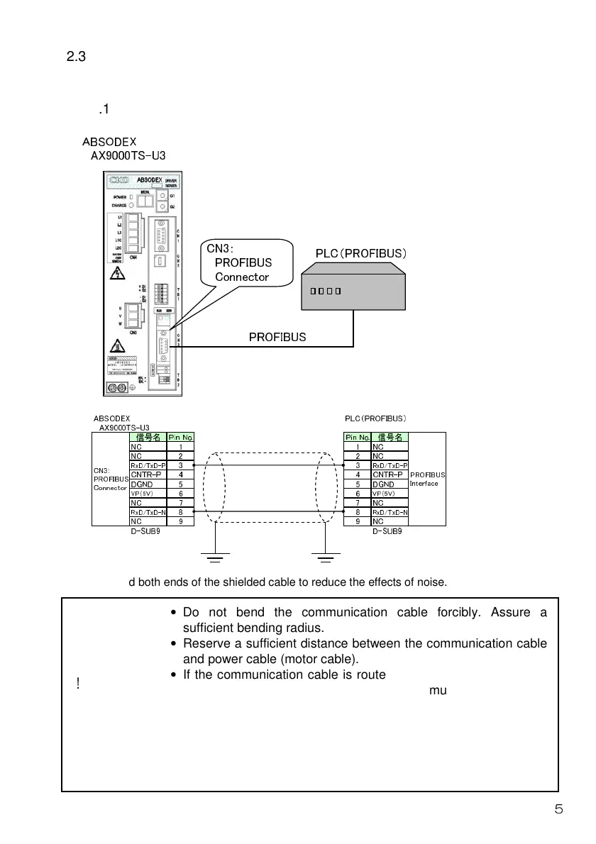
2.3 Connecting the communication cable
Connect the communication cable in the following way.
2.3.1 Connecting example to the PLC (CN3)
ABSODEX
AX9000TS-U3
PLC(PROFIBUS)
PROFIBUS
CN3:
PROFIBUS
Connector
ABSODEX PLC(PROFIBUS)
AX9000TS-U3
信号名 Pin No. Pin No. 信号名
NC 1 1 NC
NC 2 2 NC
RxD/TxD-P
3 3
RxD/TxD-P
CNTR-P 4 4 CNTR-P
DGND 5 5 DGND
VP(5V)
6 6
VP(5V)
NC 7 7 NC
RxD/TxD-N
8 8
RxD/TxD-N
NC 9 9 NC
D-SUB9 D-SUB9
CN3:
PROFIBUS
Connector
PROFIBUS
Interface
Ground both ends of the shielded cable to reduce the effects of noise.
• Do not bend the communication cable forcibly. Assure a
sufficient bending radius.
• Reserve a sufficient distance between the communication cable
and power cable (motor cable).
• If the communication cable is routed near the power cable or if
they are tied, noise will enter to make communication unstable,
possibly causing frequent communication errors and/or
communication retries.
• The connector for RS-232C (CN1) and connector for PROFIBUS
(CN3) are used differently. Pay extra attention when wiring since
the driver could break down if wired improperly.
△
CAUTION
!
 Loading...