15
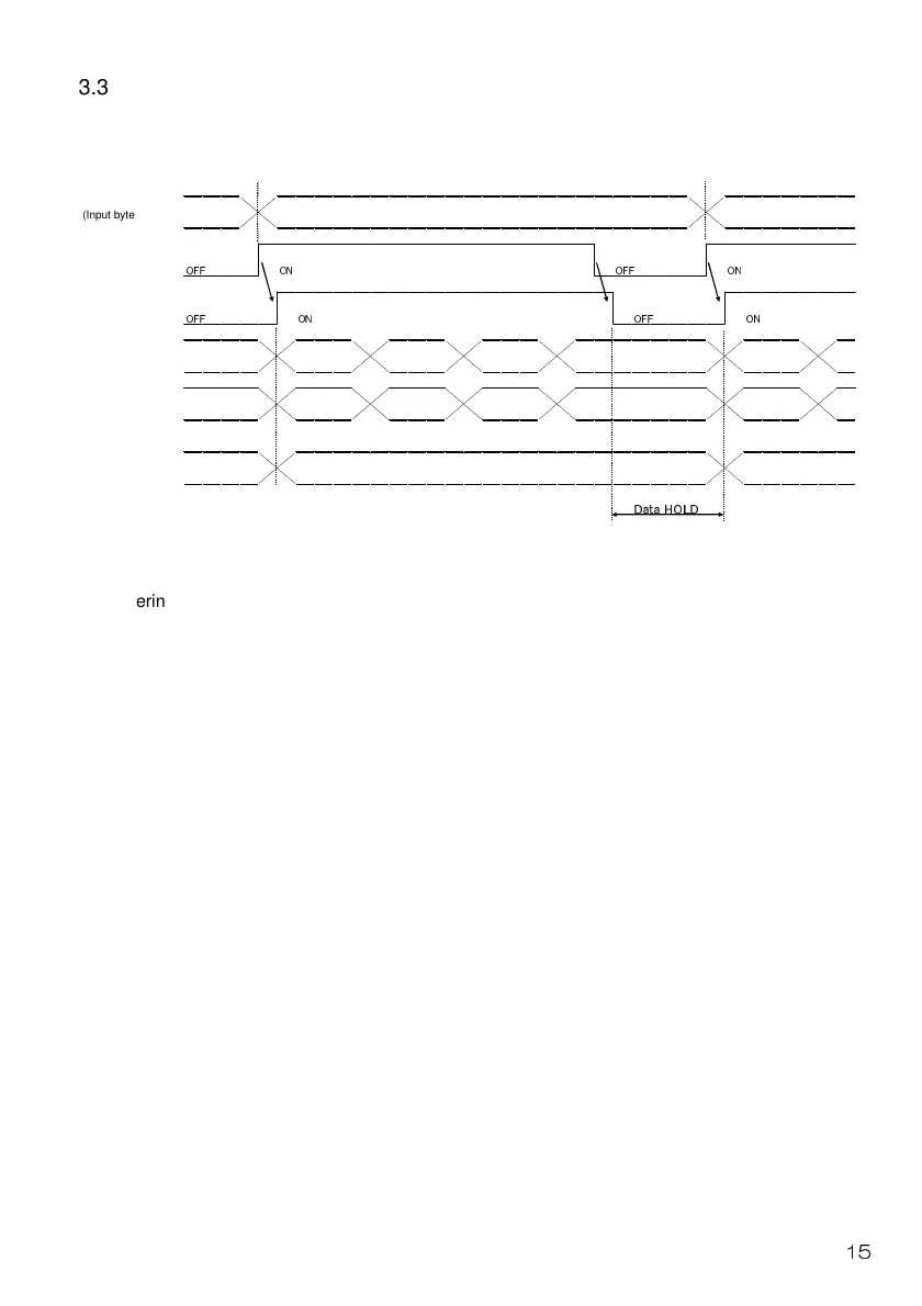
3.3 Data Communication Timing Chart
3.3.1 Monitor code
Entering monitor (Input byte 4) and monitor output execution request (Input byte 2.6) as monitor
codes will set the following data. All 16-bit data pieces will be divided into the upper 8 bits and
lower 8 bits and stored in the memory. All data is in hexadecimals. At the time, the monitoring
signal (output byte 2.6) is turned on simultaneously.
Monitor data, lower 8 bits (output byte 4):
Lower 8 bits of data requested with monitor (input byte 4)
Monitor data, upper 8 bits (output byte 5):
Upper 8 bits of data requested with monitor (input byte 4)
If there is no data at “output byte 5”, the sign is acquired. The sign is "00" in case of "+" while it is
"FF" in case of "-."
The monitor data acquired in remote registers are always updated while the monitoring signal
(output byte 2.6) remains turned on.
If the monitoring signal (output byte 2.6) is turned off, monitor data (output byte 4 and 5) will be
held.
If a monitor code not included in specifications is set on monitor (input byte 4), an error code
(1) will be set in the response code.
Monitor
(Input byte 4)
Monitor output
Execution request
(Input byte 2.6)
Monitoring
(Output byte 2.6)
Monitor data
Lower 8 bit
(Output byte 4)
Monitor data
Lower 8 bit
(Output byte 5)
Response code
(Output byte 3)
OFF ON OFF ON
OFF ON OFF ON
Data HOLD
 Loading...