8
2.4 IO interface
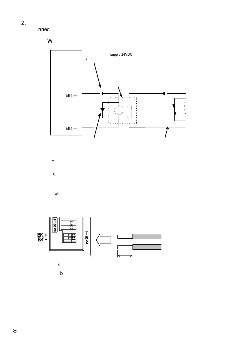
Connect "brake output (TB2)" and "emergency stop input (TB3)" in the following way.
2.4.1 Wiring of brake output (TB2)
The BK+ and BK- terminals indicate brake output terminals (rated current: Max. 150mA).
To use the electromagnetic brake, a 24VDC external power supply is necessary.
To connect above-mentioned induction loads such as the relay to the external contact, use
ones with a rated coil voltage of 24VDC and a rated current within 100mA, and take a surge
suppression measure.
Perform wiring of the electromagnetic brake so that the brake is released when the current
flows across BK+ and BK-, and it is applied when the current is stopped, without relations to
the negative or positive activation.
The cable sheath peeling length should be 9 or 10mm.
The applicable cable is AWG22 to 24 (single cable) or AWG22 to 24 (stranded cable).
BK+
BK-
External power supply 24VDC
(Prepared by customer)
External contact (relay, etc.)
(Prepared by customer)
External power supply 24VDC
(Prepared by customer)
Driver
Surge suppression measure (diode, etc.)
(Prepared by customer)
(Unnecessary in case of SSR)
Protective element
(Attached on
actuator unit)
Lead wire of electromagnetic brake
Electromagnetic
brake
9~10mm
AWG22~24
 Loading...