6
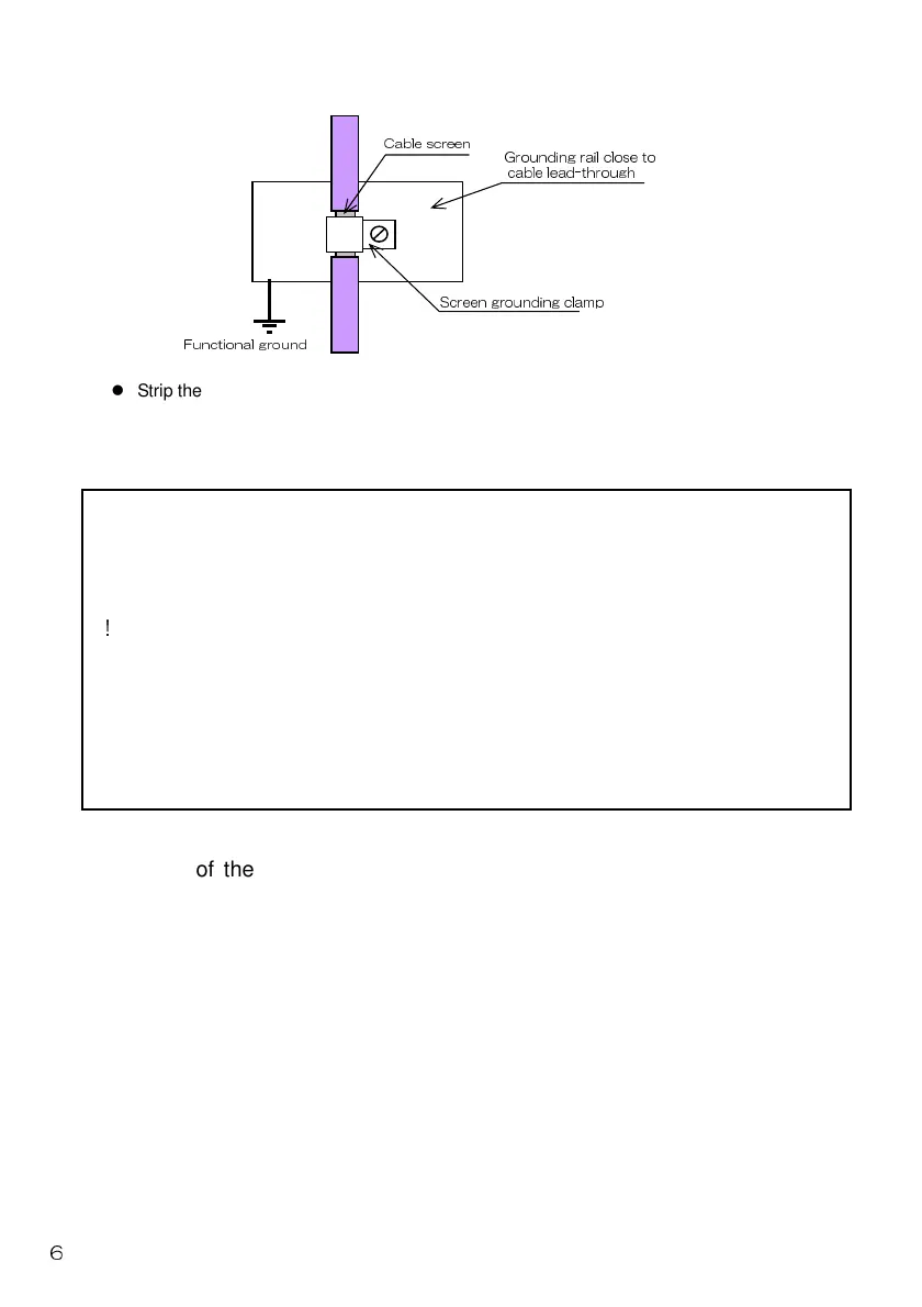
Strip the PROFIBUS cable and ground the shield section using FG clamp and such to reduce
grounding resistance.
For details of the laying of the communication cable, refer to the PROFIBUS
Laying Manual, etc.
• Be sure to use special signal cables complying with the
PROFIBUS specifications.
• For those provided with a connector fixing screw, securely
tighten the connector fixing screw when inserting the connector.
Otherwise the connector may be dislocated and cause
malfunction. For those not provided with a connector fixing
screw, check that the catch of the connector snaps in position.
• Loosen the two fixing screws before removing the connector.
The connector may be damaged if excess force is applied to the
connector without the two screws loosened.
• Remove the connector vertically to avoid excess force from
being applied to the connector.
△
CAUTION
!
Screen grounding clamp
Cable screen
Functional ground
Grounding rail close to
cable lead-through
 Loading...