Retirez la butee apres les operations ci-dessous.
1.
Retirez la vis de I'appareil pilote (Figure 5).
2.
Retirez la butee de I'appareil pilote (Figure 6),
3
Installez la vis retiree
sur
I'appareil pilote (Figure 7).
'"
Serrez la vis a
fonel.
II
Montage fixe
(TOYOTA, NISSAN
et
Clutres vehicules
equipes
ISO/DIN)
Cet appareil
est
con9u pour une installation fixe
dans
Ie tableau de
bord, Si Ie vehicule est equipe d'un auto-radio instal
Ie
a I'usine,
installer I'appareil pilote avec les pieces et les ecrous
marquees
de
(*).
(Figure 8)
Si
Ie
vehicule
n'est
pas equipe d'un auto-radio installe a I'usine
se
procurer un kit d'installation pur installer I'appareil pilote avec la
procedure suivante.
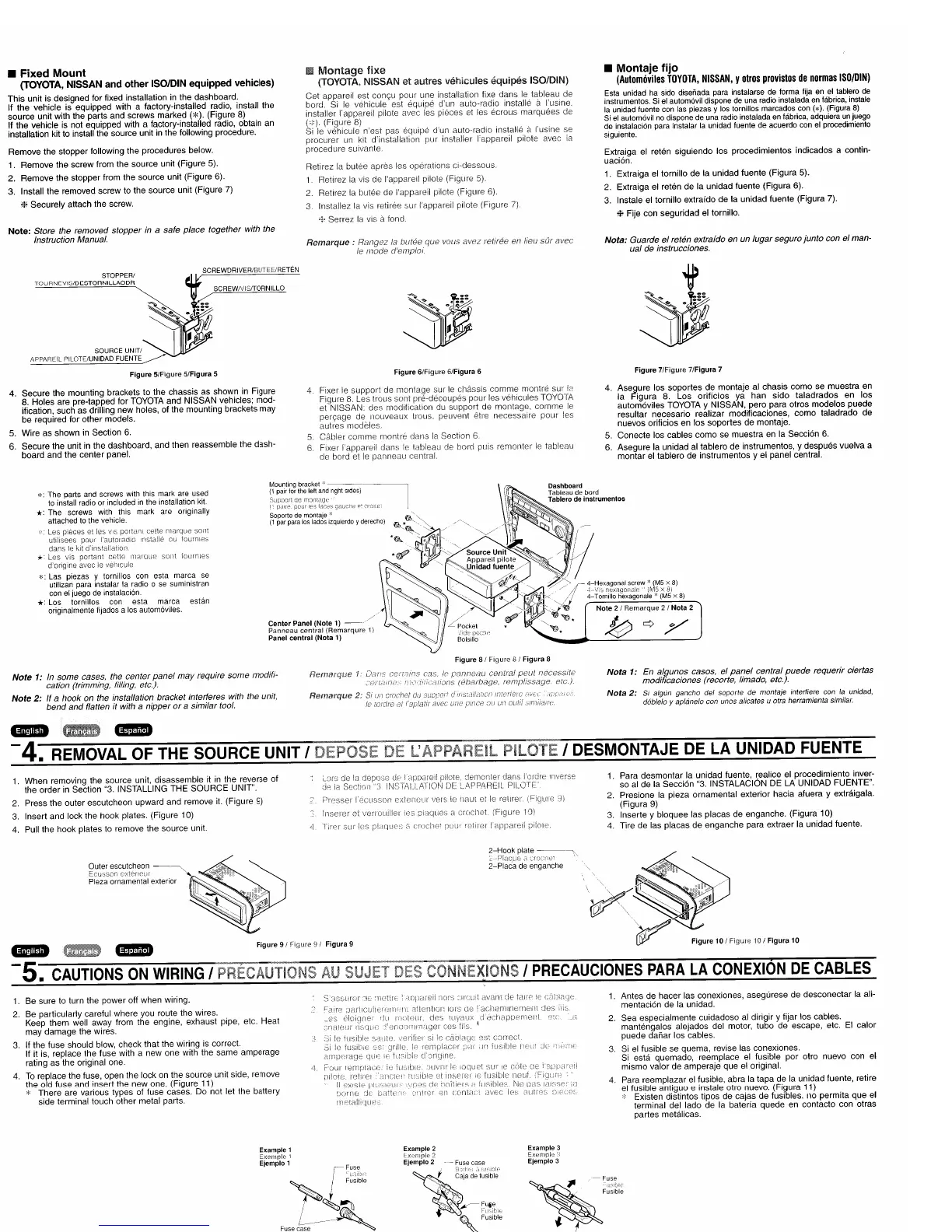
• Fixed Mount
(TOYOTA, NISSAN
and
other
ISOIDIN
equipped
vehicles)
This
unit is designed for fixed installation in the dashboard.
If
the
vehicle is equipped with a factory-installed radio, install
the
source
unit with the parts
and
screws marked
(*).
(Figure 8)
If
the
vehicle is not equipped with a factory-installed radio, obtain an
installation kit to install the source unit in the following procedure.
Remove
the
stopper
following the procedures below.
1. Remove
the
screw from the source unit (Figure 5).
2.
Remove
the
stopper from the source unit (Figure 6).
3.
Install
the
removed screw to
the
source unit (Figure 7)
*
Securely
attach the screw.
Note:
Store the removed
stopper
in a safe place together with the
Instruction Manual.
Remarque;
Ie
VOLIS
avez
retiree en lieu
sOl'
avec
• Montaje
fijo
(Automoviles
TOYOTA,
NISSAN,
Y
otros
provistos
de
normas
ISO/DIN)
Esta
unidad
ha
sido
disenada
para
instalarse
de
forma lija
en
el
tablero
de
instrumentos. 5i
el
automovil dispone
de
una
radio
instalada
en
fabrica,
instale
la
unidad
fuente
con
las
piezas y
los
tornillos marcados
con
(*).
(Figura
8)
5i
el
automovil
no
dispone
de
una
radio
instalada
en
fabrica, adquiera
un
juego
de
instalaclon
para
instalar
la
unidad
fuente
de
acuerdo
con
el
procedimiento
siguiente.
Extraiga el reten siguiendo los procedimientos indicados a contin-
uaci6n.
1. Extraiga el tornillo
de
la
unidad fuente (Figura 5).
2. Extraiga el reten de la unidad fuente (Figura 6).
3. Instale el tornillo extrafdo
de
la
unidad fuente (Figura 7).
*Fije con seguridad el tornillo.
Nota:
Guarde
el
reten extrafda en un
lugar
segura
junto
can
el
man-
ual
de instrucciones.
Figure 7/Figure 7/Figura 7
Figure
6/Figure
6/Figura 6
SCREWIVISITORNILLO
SCREWDRIVER/BUTEE/RETEN
STOPPERI
TOURNEViS/DESTORNILLAODR
SOURCE UNITI
APPAREIL PILOTE/UNIDAD FUENTE
~
Figure 5/Figure 5/Figura 5
4.
Secure
the mounting brackets
to
the
chassis
as
shown
in
Figure
8. Holes are pre-tapped for TOYOTA
and
NISSAN
vehicles; mod-
ification, such
as
drilling
new
holes,
of
the mounting brackets may
be required for other models.
5.
Wire
as
shown in Section 6.
6.
Secure
the
unit in the dashboard, and then reassemble the
dash-
board
and
the
center
panel.
4,
Fixer
Ie
support
de montage sur
Ie
chassis
comme
montre
SUI
Figure 8. Les trous sont pre-decoupes pour les vehicules TOYOTA
et NISSAN:
des
modification du support de montage,
comme
Ie
peryage de nouveaux trous, peuvent etre necessaire
pour
les
autres modeles.
5.
Cabler
comme
montre dans la Section 6
6.
Fixer dans
Ie
tableau de hard puis remonter
Ie
tableau
de
Ie
panneau central.
4.
Asegure
los
soportes
de montaje al chasis
como
se
muestra en
la
Figura
8.
Los
orificios
ya
han
sido
taladrados
en
los
autom6viles TOYOTA y
NISSAN,
pero para otros
modelos
puede
resultar necesario realizar modificaciones,
como
taladrado
de
nuevos orificios
en
los
soportes
de
montaje.
5. Conecte los cables
como
se
muestra en la Secci6n 6.
6.
Asegure la unidad al
tablerc
de instrumentos, y despues vuelva a
montar
el tablero
de
instrumentos
y el panel central.
*:
The
parts
and
screws
with
this
mark
are
used
to
install
radio
or
included
in
the
installation
kit.
*:
The screws with this mark are originally
attached
to
the
vehicle.
Les pieces et les portan: celte
utilisees I'autoradio
Instaiie
dans
ie
*'
Les vis ponant cette rnarQue SOllt
fourni8s
d'origine
avec
Ie
ve"'cule
*:
Las
piezas y tornillos
con
esta marca
se
utilizan
para
instalar
la
radio
0
se
suministran
con
el
juego
de
instalaci6n.
*:
Los
tornillos
con
esta marca estan
originalmente fijados a
los
autom6viles.
Mounting
bracket
'"
--------~
(1
pair
for
the
lett
and
right
Sides)
pour
p.
(irOile
Soporte
de
montaje
'"
(1
par
para
los
lados
Izquierdo
y
derecho)
Center
Panel
(Note
1)
Panneau
central
(Remarqure
1)
Panel
central
(Nota
1)
Dashboard
Tableau
de
bord
Tablero
de
instrumentos
#>(
4-Hexagonaf
screw
-
(M5
x 8)
--+
\
:,
r)8X811C'11de
1M:'
x
til
,/
4-T
omilio
hexagon
ale
'(M5 x 8)
~
..
,:'(B
Note
2 1
Remarque
2 1
Nota
2
~"r§*"@*
~
q y
Note
1: In
some
cases, the
center
panel
may
require
some
modifi-
cation (trimming, filling, etc.).
Note
2:
If
a
hook
on the installation bracket intet1eres with the
unit
bend
and
flatten it with a
nipper
or
a similar tool.
Remarqui'!
Nota
1: En algunos casas,
el
panel
central
puede
requerir ciertas
modificaciones (recorte, /imado! etc.).
Nota
2:
5i algun gancho del soporte de montaje intertlere con
la
unidad,
d6blelo
y ap/anelo con
un
os alicates u otra herramienta similar.
q.@I.I.i.
-
4.
REMOVAL OF THE SOURCE UNIT
'DEPOSE
DE
L'APPAREIL
PILOTE'
DESMONTAJE
DE
LA
UNIDAD FUENTE
1.
Para
desmontar
la unidad fuente,
~ealice
el procedimiento inver-
so
al
de
la Secci6n "3. INSTALACION DE LA UNlOAD FUENTE".
2. Presione la pieza ornamental exterior hacia afuera y extraigala.
(Figura
9)
3. Inserte y bloquee las placas de enganche. (Figura 10)
4. Tire de las placas de enganche para extraer la unidad fuente.
demonler dans I'ordre Iilverse
! APP!il.RiF!!
PILOTE
vers Ie ili'\ur et Ie retlr8l'
lnserer et veriOuiller les piaques
crochet
(Figure I
oJ)
lappareil
pilote,
LJrs de
la
;Jo
12
Section
1.
When
removing
the
source unit, disassemble it in
the
reverse of
the
order
in Section "3. INSTALLING
THE
SOURCE
UNIT".
2. Press
the
outer escutcheon upward
and
remove it. (Figure 9)
3. Insert and lock the
hook
plates. (Figure 10)
4.
Pull
the
hook plates to remove
the
source
unit.
Outer escutcheon
-~
Ecusson extsncu!
Pleza
ornamental exterior
2-Hook
plate
-----"
~',---··Plaoue
\,
2-Placa
de
enganche
ftIO'I
_
q.ijUl.!.
Figure
91
Figure
91
Figura 9
Figure
101
Figure
101
Figura
10
-5.
CAUTIONS
ON
WIRING'
PRECAUTIONS
AU
SUJET
DES
CONNEXIONS
I
PRECAUCIONES
PARA
LA
CONEXION
DE
CABLES
1.
Be sure to turn the
power
off when wiring.
2. Be particularly careful where you route
the
wires.
Keep
them
well away from the engine, exhaust pipe, etc. Heat
may
damage
the wires.
3. If
the
fuse should blow,
check
that
the
wiring is correct.
If it is, replace
the
fuse with a
new
one
with the same
amperage
rating
as
the original one,
4.
To
replace the fuse, open
the
lock on
the
source
unit side, remove
the
old fuse and insert
the
new one. (Figure 11)
*
There
are various types of fuse cases. Do not let the battery
side terminal touch
other
metal parts.
1. Antes
de
hacer
las conexiones, asegurese
de
desconectar
la ali-
mentaci6n de la unidad.
2. Sea especialmente cuidadoso al dirigir y fijar los cables.
mantengalos alejados del motor,
tubo
de
escape, etc.
EI
calor
puede
danar
los cables.
3.
Si el fusible
se
quema, revise las conexiones.
Si esta quemado, reemplace el fusible
por
otro nuevo con el
mismo
valor de amperaje que el original.
4. Para reemplazar el fusible, abra la
tapa
de la unidad fuente, retire
el fusible antiguo e instale otro nuevo. (Figura
11)
'"
Existen distintos tipos de cajas
de
fusibles.
no
permita
que
el
terminal del lado de la bateria
quede
en contacto con otras
partes
metalicas.
Example
2
Lxernpie
:::
Ejemplo
2 - -
Fuse
case
~
f.~
..
i
.•.
cEl.a.·':~'d~if~~~;~
!
~
. 1
"
,:.~
~FlJie
f:"
~'P
'),
Fu<biE;
,usible
Example
3
Exernpk
'-!
Ejempfo
3
.-
Fuse
~
;~:ig::
~
L Fuse case
!';;,I
Figure
11
I 1
Figura
11
Cafa
de
 Loading...