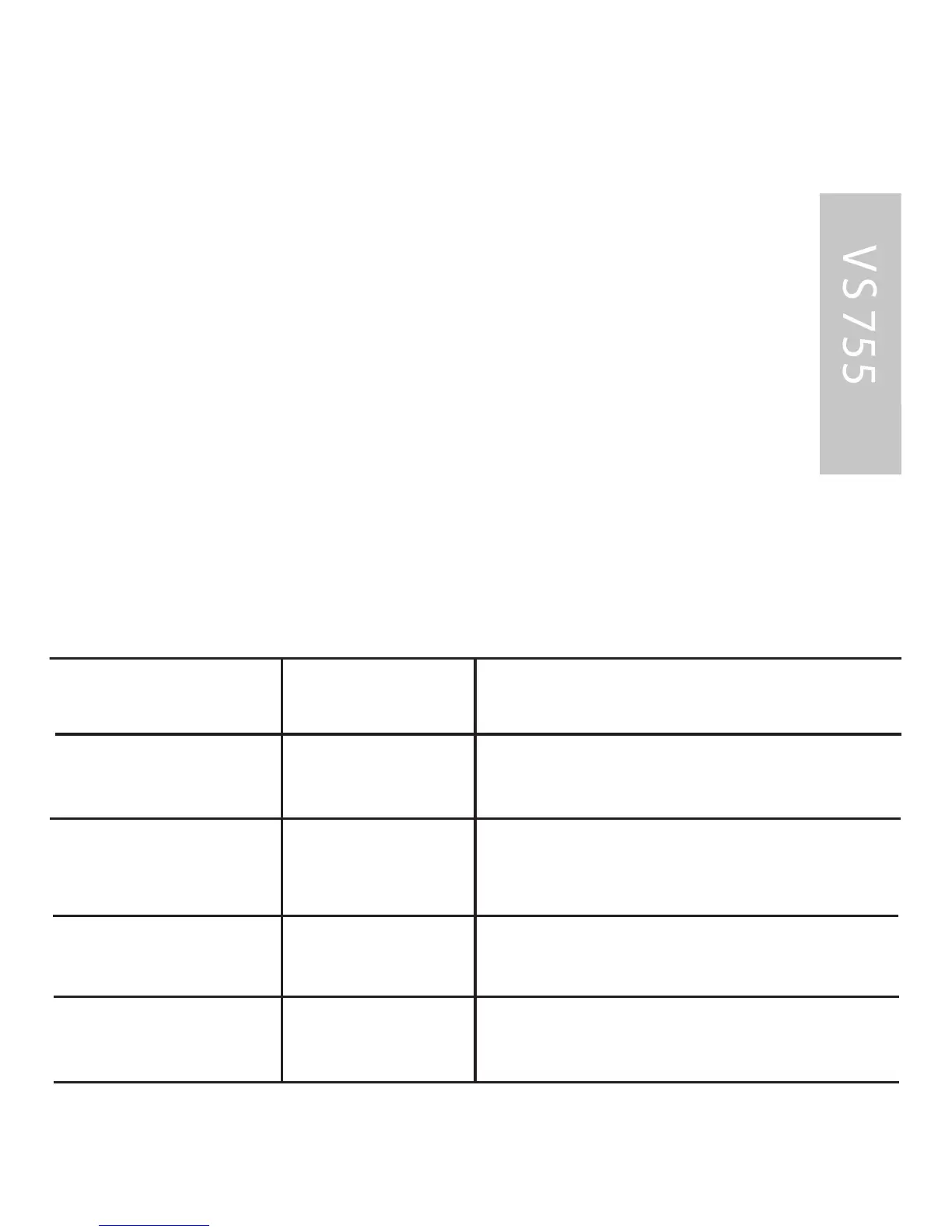
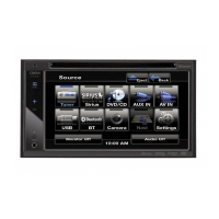
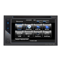
INS TAL L AT ION
E lectrical connec tions .
R oute all cables with care.
Do not cut off un-us ed cables,
tape them up and s ecure
them to one s ide. T hey may
be useful in the future for
additional functions.
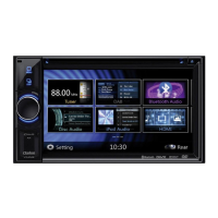
P ower s upply connections
C able color C ategory C onnection
Yellow input +12v permanent positive
(mus t be rated for at least 3 amps)
R ed
input +12v ignition pos itive
(switched plus)
B lack
input
B attery negative
(vehicle chassis)
B lue
output
Auto antennal
R emote control power
If the yellow +12v permanent
positive lead is lengthened and
connected directly to the battery,
it must be protected by
an additional
10 Amp fuse located near the
battery (max.10-15 cm)
+12 V constant lead (yellow):
C onnect the yellow lead to a
suitable connector with +12v
permanent positive voltage.
This connection should be rated
for a current of at leas t 3 amps.
+12 V switched lead (red):
C onnect the red lead to a suitable
+12v circuit switched through
the ignition.
B attery negative lead (black):
C onnect the black lead to a
suitable ground
(vehicle chassis).
47
input