1-4 EF-701M INTERFACE
converted to go over the chosen transmission medium, it must be reconverted to 2-wire
mode to properly connect to the party-line system or station at the other end of the line.
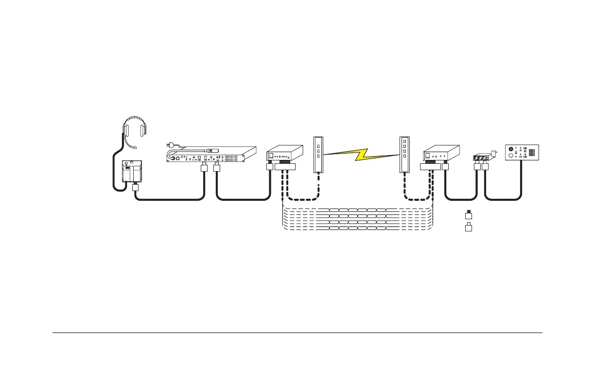
The EF-701M obtains its DC operating current from the local party-line connection on
pin 2 of the XLR connector. This current is not conducted between EF-701M units, so
each EF-701M must be powered by an intercom line as shown in Figure 1-2.
Figure 1-2: Each EF-701M unit must be powered by an intercom line
Call signaling can serve as more than simply a visual indicator. A call signal can activate
relays and trigger functions in other connected Clear-Com equipment. The Clear-Com
TW-47 Two-Way Radio Interface and KB-702 Speaker Station use this feature. Imagine a
party-line (PL) system connected to a fiber-optic system over a 1-kilometer fiber as shown
3
3
= Male 3-Pin XLR
= Female 3-Pin XLR
Party-Line Intercom EF-701M
EF-701M
Fiber Modems
Party-Line Intercom
Cat 3 or Cat 5
Twisted Pair
3
DB15
3
3
3
3DB15
3
3