31
APPENDIX B: MULTIPLE BASE STATION DAISY-CHAINING
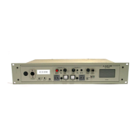
Two or more DX410 base stations can be “daisy-chained” together with cables connected to the 2-W connectors on the
rear panels of each base station (following Clear-Com
®
/ RTS
®
standards), or two base stations (not more) can be “daisy-
chained” together with cables connected to the 4-W or AUX connectors.
A maximum of 4 base stations can be used in one system, spaced apart a minimum of 12 inches.
NOTE 1: DX410 does not provide 2-wire line power, therefore, 2-wire power bypass must be used.
RTS
®
Mode Clear-Com
®
Mode
Pin 1 = Common Pin 1 = Common
Pin 2 = Channel 1 Pin 2 = N/C
Pin 3 = Channel 2 Pin 3 = Audio
2-WIRE
Female
2-WIRE
Male
NOTE 2: For AUX type daisy-chaining, the cable connectors must be 3-pin XLR.
h If using 4-wire connection, use cable with In/Out crossed, as shown to the
right. (An Ethernet crossover cable will not work.)
h If using 2-Wire connections, open each base station and set jumpers JP1
(A) and/or JP2 (B) in all base stations to ON for power detect bypass. Set
jumpers JP5 (A) and/or JP6 (B) in only one base station per channel for
termination. Refer to Appendix C, next page.
A/B In + ─── A/B Out +
A/B In – ─── A/B Out –
A/B Out + ─── A/B In +
A/B Out – ─── A/B In –
2 Base Stations More than 2 Base Stations
2-Wire connection
Base-to-Base communication via IC
A
2-W
B
2-W
2-Wire connections only
Base-to-Base communication via IC
A
2-W
B
2-W
A
2-W
A
2-W
B
2-W
B
2-W
AUX connection
Base-to-Base communication via ISO
AUX
4-Wire connection
Base-to-Base communication via IC
A
4-W
B
4-W
1
1
2 2
3
3

 Loading...