17
Interfacing with 2-Wire or 4-Wire Intercoms
2-Wire Intercom Interface
The following 2-wire setup is for Channel 1 (A). If applicable, repeat for Channel 2 (B).
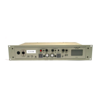
h If using a 2-wire intercom with the DX410, plug it into the base station 2-W connector at (
2
) or (
3
),
depending on whether a male or female connection is required.
h Depending on whether you are using a Clear-Com
®
or RTS
®
compatible 2-wire intercom system, position the
CLEAR-COM / RTS button (
4
) as follows: In position = RTS Mode Out position = Clear-Com Mode
h Press the A SELECT button on the front panel of the base station. The 2-W light next to the button should
turn green.
NOTE: If no power is detected at the 2-W connector, the 2-W light will illuminate red and no audio will be
passed through. Plugging a connection into a Clear-Com or RTS power supply will turn the light green and
operation will begin.
h Make certain there are no open microphones on the wired intercom. If users are wearing headsets, please
notify them of the impending audio sweep prior to auto nulling.
h Press and hold the AUTO NULL button for two seconds. To press the AUTO NULL button, insert a pen or
similar pointed object into the AUTO NULL hole on the front panel of the base station. An audio sweep will
be heard for 25 seconds on the wired Belt Packs. (The 2-W light next to the button should turn amber, then
green.)
h Adjust the 2-W intercom receive and send levels with the A 2-W INPUT control and OUTPUT control.
NOTE: If you are not connecting other equipment, go on to System Operation (pg. 20).
4-Wire Intercom Interface
The following 4-wire setup is for Channel 1 (A). Repeat for Channel 2 (B) if applicable.
h If using a 4-wire intercom with the DX410, plug it into the base station A
4-W connector (
1
).
h Press the respective SELECT button until the A 4-W light next to the
button goes on.
h Adjust the 4-wire intercom receive and send levels with the A 4-W INPUT
and OUTPUT controls.
1 2 3 4
Base station rear panel
RJ45 Connector Pins Designation
Pins 1, 2, 7 and 8 N/C (reserved)
Pin 3 Intercom Out +
Pin 4 Intercom In +
Pin 5 Intercom In –
Pin 6 Intercom Out –

 Loading...