750-368
CBEX Elite 100-1200 HP
6-13
6.15 — Burner Drawer Adjustment
6.15 — Burner Drawer Adjustment
There are relatively few adjustments that can be made to the burner, however,
a check should be made to assure that all components are properly located,
and that all holding screws are properly tightened.
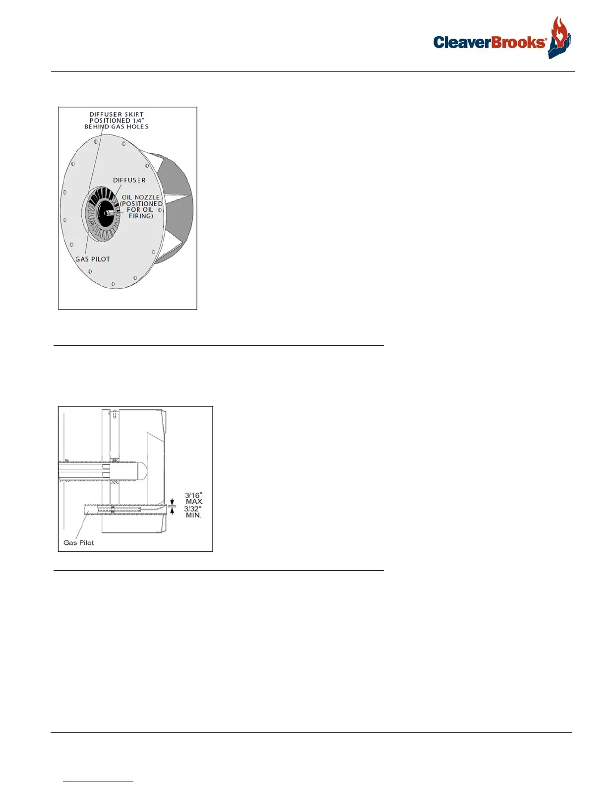
The diffuser location on gas fired boilers is important. There should be 1/4” dis-
tance between the edges of the diffuser fins and gas outlet tubes (spuds) com-
ing from the burner housing. The setting of an oil fired burner is less exacting
and the diffuser should be located with the diffuser skirt approximately 1-1/8”
in front of the oil nozzle.
When the proper diffuser location is ascertained, the setting of the nozzle in
relation to the diffuser should be checked. This generally is set at time of man-
ufacture and seldom needs altering. It is most important that oil spray does not
impinge upon the diffuser. The distance that the nozzle is behind the diffuser
has some latitude, and individual installation may require a slight deviation.
FIGURE 6-7. Burner Drawer Adjustments
Check the setting of the ignition electrode(s) for proper gap and position. Be sure that the porcelain insulator is
not cracked and that ignition cable connections are tight.
The oil nozzle tip should be seated tightly in the body with the swirler and
the seating spring in place.
Check to see that the flame detector sight tube and the gas pilot tube extend
through their respective openings in the diffuser face.
FIGURE 6-8. Gas Pilot Electrode
6.16 — Oil Drawer Switch
The integral contacts of the control are closed by proper positioning and latching of the oil nozzle lance in its for-
ward position. Adjustment of the switch must be such that its contacts open if the oil nozzle lance is not properly
positioned for oil firing. The switch is electrically removed from the circuit when a combination fuel burner is fired
on gas (fuel selector switch is in GAS position).