750-368
CBEX Elite 100-1200 HP
2-3
2.3 — Gas System
The flame detector portion of the control monitors both oil and gas flames and provides protection in the event of
loss of a flame signal.
The control recycles automatically during normal operation, or following a power interruption. It must be manu-
ally reset following a safety shutdown caused by a loss of flame. An internal checking circuit, effective on every
start, prevents burner operation in the event anything causes the flame relay to hold in during this period.
2.3 — Gas System
Depending upon the requirements of the insurance carrier or other governing agencies, the gas flow control sys-
tem, or gas train, may consist of some, or all, of the following items. Refer to the Dimension Diagram (DD) pre-
pared by Cleaver-Brooks for the installation.
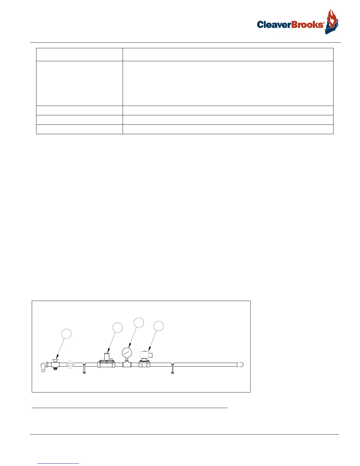
Item numbers refer to the table following the illustrations.
FIGURE 2-2. Pilot Gas Train
7. Control panel Houses the touchscreen HMI and boiler control system. Controller automatically
programs each starting, operating, and shutdown period in conjunction with oper-
ating limit and interlock devices. Includes, in a timed and proper sequence, the
operation of the blower motor, ignition system, fuel valve(s), damper, and FGR.
The sequence includes air purge periods prior to ignition and upon burner shut-
down.
8. Entrance box Houses high voltage equipment including motor starters and fuses.
9. Gas train See 2.3
10. Oil system See 2.4
Component Description