CFC-E Installation Manual
1-16 Part No. 750-459
1.5.6 - Gas Header
Design of a single common gas header with individual takeoffs for a multiple unit installation is
recommended. Boiler gas manifold piping should be sized based on the volume requirements and
lengths between boilers and the fuel main headerFigure .
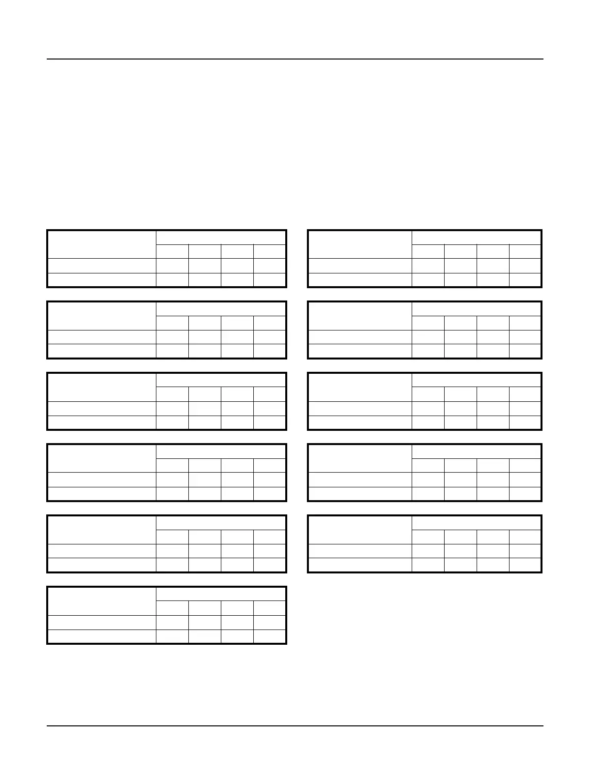
Table 1-8 indicates the proper sizing for multiple units, and assumes < 1 psig supply pressure with units
placed on the factory standard center with the indicated take off size. Contact CB for other boiler sizes.
For installations with a mixed sized use, determine the flow of each unit and total the input. With the
total input, determine length of run from the source and determine what size header will be needed for
the flow of all units firing. Pipe sizes based on Table 1-6.
Table 1-8: Piping for Multiple Unit Manifolds - Natural Gas
CFC-E 500
Number of Boilers
CFC-E 750
Number of Boilers
1234 1234
Pipe size to boiler 1”1”1”1” Pipe size to boiler 1”1”1”1”
Header pipe size 1-1/4” 1-1/4” 1-1/2” 2 Header pipe size 1-1/4” 1-1/2” 2” 2-1/2”
CFC-E 1000
Number of Boilers
CFC-E 1500
Number of Boilers
1234 1234
Pipe size to boiler 1-1/4” 1-1/4” 1-1/4” 1-1/4” Pipe size to boiler 1-1/2” 1-1/2” 1-1/2” 1-1/2”
Header pipe size 1-1/4” 2” 2” 2-1/2” Header pipe size 1-1/2” 2” 2-1/2” 3”
CFC-E 2000
Number of Boilers
CFC-E 2500
Number of Boilers
1234 1234
Pipe size to boiler 2”2”2”2” Pipe size to boiler 2”2”2”2”
Header pipe size 2” 2-1/2” 3” 3” Header pipe size 2” 3” 3” 4”
CFC-E 3000
Number of Boilers
CFC-E 3500
Number of Boilers
1234 1234
Pipe size to boiler 2-1/2” 2-1/2” 2-1/2” 2-1/2” Pipe size to boiler 2-1/2” 2-1/2” 2-1/2” 2-1/2”
Header pipe size 2-1/2” 3” 4” 4” Header pipe size 2-1/2” 3” 4” 4”
CFC-E 4000
Number of Boilers
CFC-E 5000
Number of Boilers
1234 1234
Pipe size to boiler 2-1/2”2-1/2”2-1/2”2-1/2” Pipe size to boiler 3” 3” 3” 3”
Header pipe size 2-1/2” 3” 4” 4” Header pipe size 3” 4” 4” 5”
CFC-E 6000
Number of Boilers
1234
Pipe size to boiler 3”3”3”3”
Header pipe size 3” 4” 5” 5”