CFC-E Installation Manual
1-2 Part No. 750-459
1.1 - Boiler Placement
The Model CFC-E boiler is shipped fully assembled, ready for installation. There may be accessories
that ship loose for field installation and wiring. Refer to specific order information for details.
For handling instructions specific to larger sizes (3500-6000) see document CB-8597.
1.1.1 - Lifting by the base
The boiler can be lifted by the base using a suitable fork lift or
pallet jack. When possible, forks should extend through to the
other side for proper support.
Note: The boiler should not be moved by pushing, prying, or
pulling on any part of the casing. To avoid damage to casing,
removal of front and side casing panels is recommended
during installation. DO NOT attempt to lift the boiler by the four
7/16” holes at the base; these are for seismic mounting only.
1.1.2 - Lifting with crane (500-3000)
The boiler can be lifted from the top after first removing the
casing and burner.
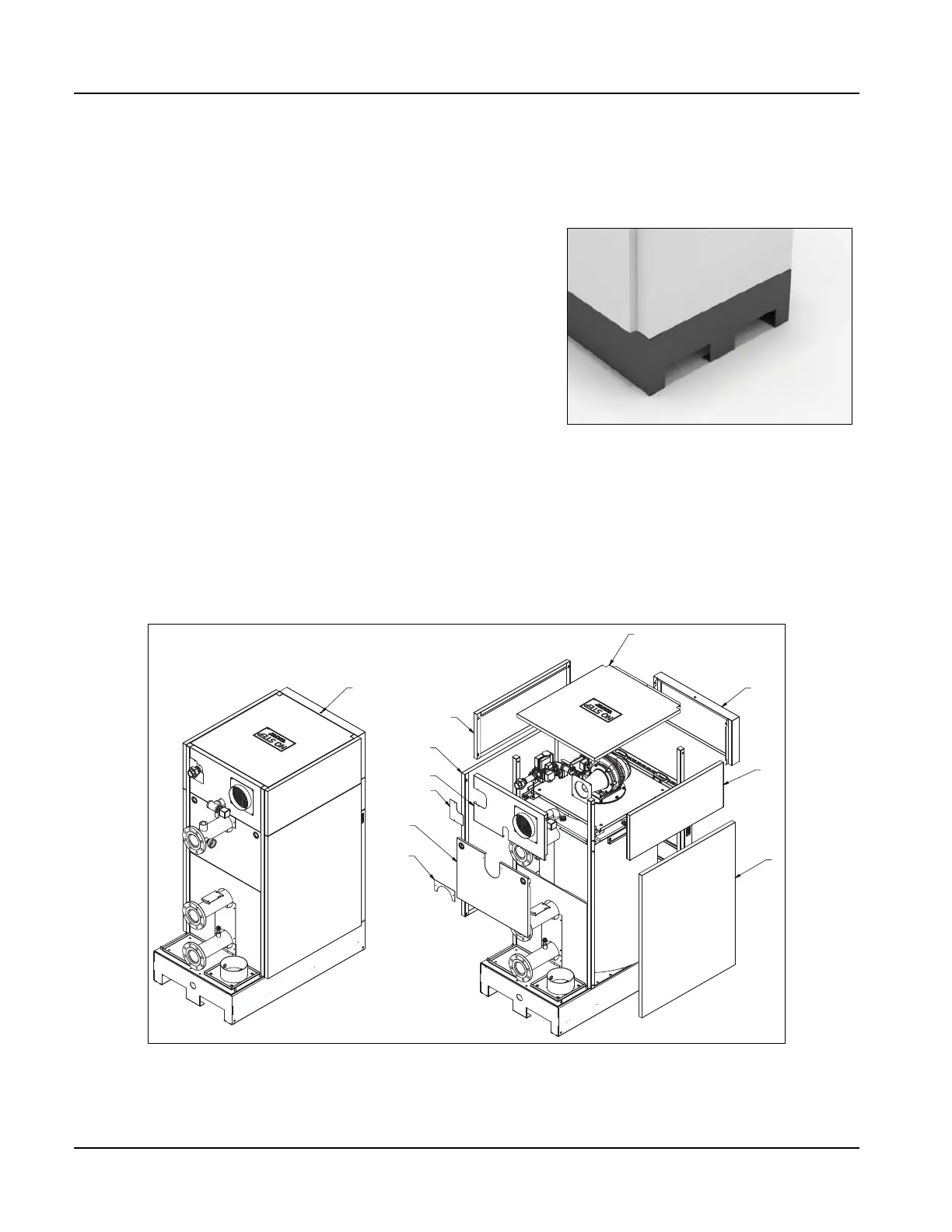
1.To remove casing panels, remove screw located on top of upper front panel (above Cleaver-Brooks
logo). Follow Figure 1-2 for panel removal sequence. Panels 1, 3, 4, 6, and 8 must be removed by lifting
up and pulling out from boiler. Panel 2 (roof) can be lifted off boiler once panel 1 has been removed.
2.Store panels in safe location to ensure they are not damaged.
Figure 1-2 Casing removal