Chapter 1 GENERAL DESCRIPTION
1-4 750-177
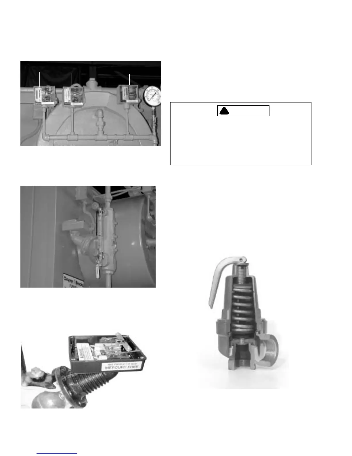
Figure 1-3: Steam Controls
Figure 1-5: Low Water Cut Off Pump Control
(Cutaway)
avoid overtightening, which can distort the seats. Use
only flat-jawed wrenches on the flats provided. When
installing a flange-connected valve, use a new gasket and
draw the mounting bolts down evenly. Do not install or
remove side outlet valves by using a pipe or wrench in
the outlet.
!
DANGER
WARNING
Only properly certified personnel such as
the safety valve manufacturer’s certified
representative can adjust or repair the
boiler safety valves. Failure to follow these
instructions could result in serious
personal injury or death
E. Hot Water Controls (All Fuels)
1. Water Temperature Gauge (Figure 1-7): Indicates the
boiler internal water pressure.
2. Water Pressure Gauge (Figure 1-7): Indicates the internal
pressure of the boiler.
3. Operating Limit Temperature Control (Figure 1-7):
Breaks a circuit to stop burner operation on a rise of
boiler temperature at a selected setting. It is adjusted to
1. HIGH LIMIT PRESSURE CONTROL
2. OPERATING LIMIT PRESSURE CONTROL
3. MODULATING PRESSURE CONTROL
12
3
Figure 1-4: Low Water Cut Off (LWCO)
Figure 1-6: Safety Valve Cutaway