Chapter 2 ProFire Burner Operation and Control
2-2 750-177
Table 2-1: Combustion Air Flow Requirements
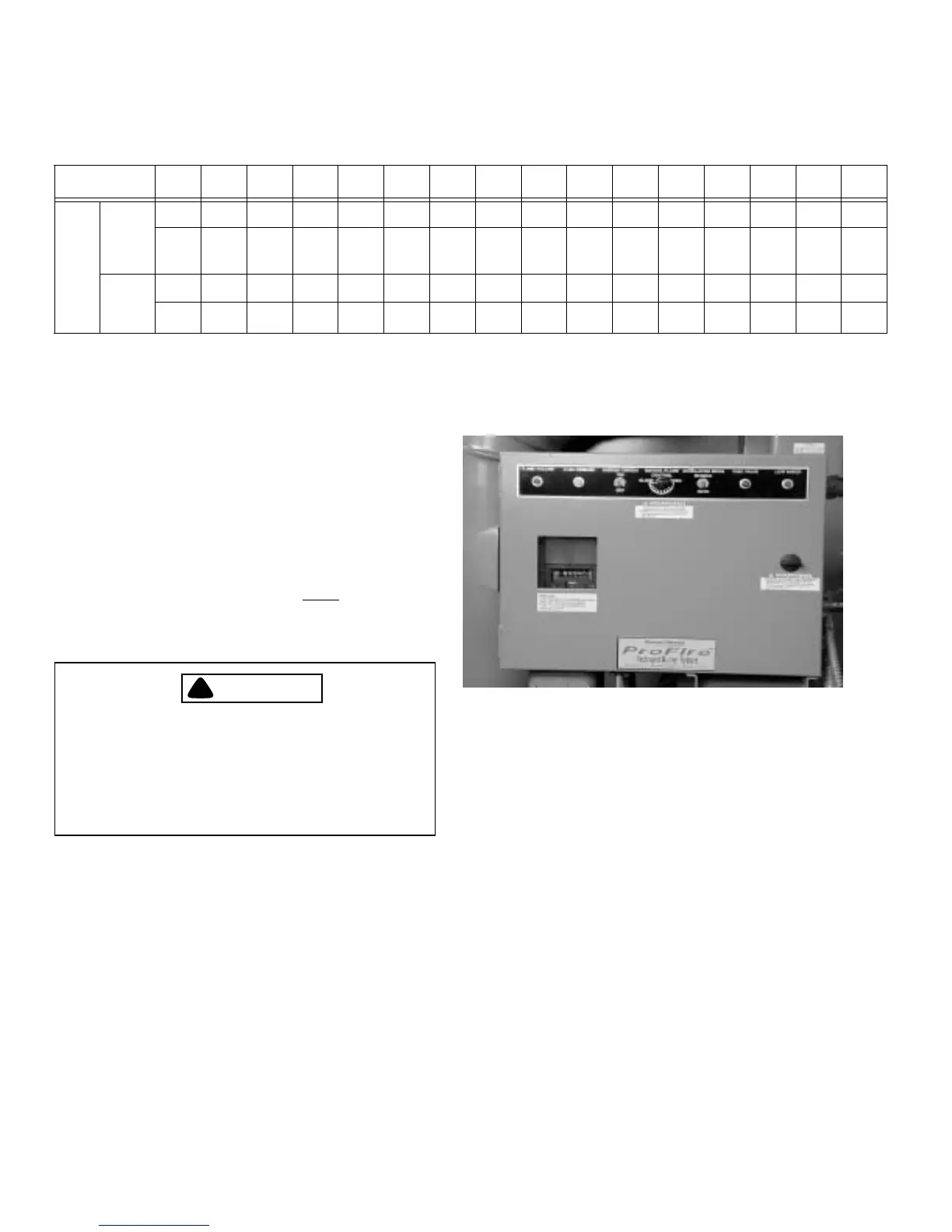
Figure 2-1: Control Cabinet
indicates a blower housing “down” unit that burns only
natural gas; it is made of size-two components, and is rated
for 3.5 MMBtu/hr fuel input at high fire and is configured to
meet IRI (Industrial Risk Insurers) standards.
C. RECOMMENDED FUELS AND
VENTILATION
ProFire burners are designed to burn either natural gas or
light oil (#2), as defined by ASTM D396 - 1978 specification.
!
DANGER
WARNING
This burner is designed to burn only those
fuels shown on the burner data plate.
Burning fuels not specified on the data plate
could cause damage to the equipment, or
can result in serious personal injury or
death.
Note: Structural enclosures for this
equipment must be configured to allow
ample flow of combustion and ventilation
air. See Table 2-1 for combustion air volume
requirements.
D. CONTROLS AND COMPONENTS
The burner can be equipped with special operating controls,
various types of flame safeguard systems, and/or a system to
minimize NOx emissions. The wiring and dimension
diagrams and construction reference list (available with the
burner) confirm the specific features and equipment included.
Refer to Figures 2-1 and 2-2 for component locations. The
following list describes components and basic functions of
the burner.
1. Electrical Control Cabinet (Figure 2-1): The control
cabinet houses many of the electrical control
components and the flame safeguard. The operator
control switches and indicator lights are located on the
face of the control cabinet door. The following controls
and indicators are provided:
• Flame Failure Light: Illuminates (red) 20 sec-
onds after the flame is extinguished. When this
happens, the system automatically shuts down;
manual reset of the flame safeguard is required.
• Load Demand Light: Illuminates (white) when
A. FLAME FAILURE LIGHT
B. LOAD DEMAND LIGHT
C. BURNER SWITCH
D. MANUAL FLAME CONTROL
E. MANUAL-AUTO SWITCH
F. FUEL VALVE LIGHT
G. LOW WATER LIGHT
ABC
D
EFG
8
MODEL NO. 150 200 250 300 350 400 450 500 550 600 700 800 900 1000 1100 1200
Comb
Air
(Dry)
Gas
(scfh)
(lb/hr)
15480 20640 25800 30960 36120 41280 46440 51600 56760 61920 72240 82560 92280 103200 113520 123840
1207 1609 2012 2414 2817 3219 3621 4024 4426 4828 5633 6438 7243 8048 8853 9658
Oil (scfh)
(lb/hr)
17050 22733 28414 34098 39782 45463 51146 56831 62514 68196 79562 90928 102294 113662 125028 136394
1269 1692 2115 2538 2961 3384 3807 4231 4654 5077 5923 6769 7640 8462 9308 10154
NOTES:
1. Natural gas @ 1000 Btu/cu-ft.
2. No. 2 oil @ 140,000 Btu/gal.