ProFire Burner Operation and Control Chapter 2
750-177 2-3
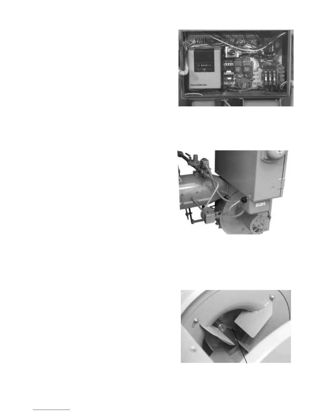
Figure 2-4: Impeller
A. FLAME SAFEGUARD
B. FUEL SELECTION SWITCH
the boiler operating controls indicate a demand
for hot water or steam.
• Burner Switch: Activates or deactivates the op-
erating cycle of the flame safeguard control.
• Manual Flame Control: When in Manual Mode,
it provides manual adjustment of the burner fir
-
ing rate between low-fire and high-fire opera-
tion.
• Manual-Auto Switch: Allows the operator to
override the automatic boiler controls for manual
firing rate adjustment.
• Fuel Valve Light: Illuminates (green) when the
selected fuel valve is energized.
• Low Water Light: Illuminates (red) when the
boiler low-water cutoff control is activated.
2. Flame Safeguard (Figure 2-2): The flame safeguard
controls the operating sequences of the combustion
system (prepurge, pilot, firing, and shutdown). The
control also monitors the flame, using a scanner which is
sensitive to specific flame frequencies. The flame
safeguard also automatically shuts down the burner
when the flame signal becomes too weak. Different types
of flame safeguard devices can be installed in the
combustion systems. Check the wiring diagram for your
burner for information on the specific unit installed on
your burner.
3. Fuel Selection Switch (Figure 2-2): Allows the operator
to select either gas or oil as the active fuel on
combination burners. (The switch is located inside the
control cabinet.)
4. Pilot Gas Train (Figure 2-3). The standard pilot gas train
consists of a manual stopcock, a gas pressure regulator,
and a solenoid-operated gas shut-off valve. The gas pilot
valve assembly controls a relatively small flow rate of
natural gas to operate the gas-electric pilot.
5. Blast Tube (Figure 2-3). The blast tube functions as a
duct for combustion air, and houses the fuel nozzle(s),
gas pilot assembly, diffuser, and air baffle assemblies.
6. Blower Housing (Figure 2-3). The blower housing
encloses the impeller. The fan drive motor is mounted
directly to the blower housing.
7. Combustion Air Fan Motor (Figure 2-3). The electric
motor drives the combustion air fan and the oil pump (if
so equipped).
8. Ignition Transformer (Figure 2-3). The ignition
transformer produces the high voltage required for spark
generation by the pilot electrode(s).
9. Combustion Air Proving Switch (Figure 2-3). The
combustion air proving switch provides confirmation to
the flame safeguard that the combustion air fan is
A
B
Figure 2-2: Control Cabinet (Open)
A. PILOT GAS TRAIN
B. BLAST TUBE
C. BLOWER HOUSING
D. COMBUSTION AIR FAN MOTOR
E. IGNITION TRANSFORMER
F. COMBUSTION AIR PROVING SWITCH
Figure 2-3: ProFire Burner (Left Side)
A
B
C
D
E
F