Chapter 2 ProFire Burner Operation and Control
2-4 750-177
A. LOW-FIRE SHUTTER
B. HIGH-FIRE SHUTTER
C. AIRBOX
D. MAIN AIR SHUTTER SHAFT
providing air flow. The fuel supply valves will not open
if this switch does not sense adequate air pressure.
10. Impeller (Figure 2-4). The impeller is designed with
backwards-inclined vanes. It is located inside the blower
housing, and is driven by the combustion air fan motor.
The impeller provides combustion air to the burner
assembly. Removing the impeller requires the use of the
impeller puller, part number 943-388 (Figure 2-8)
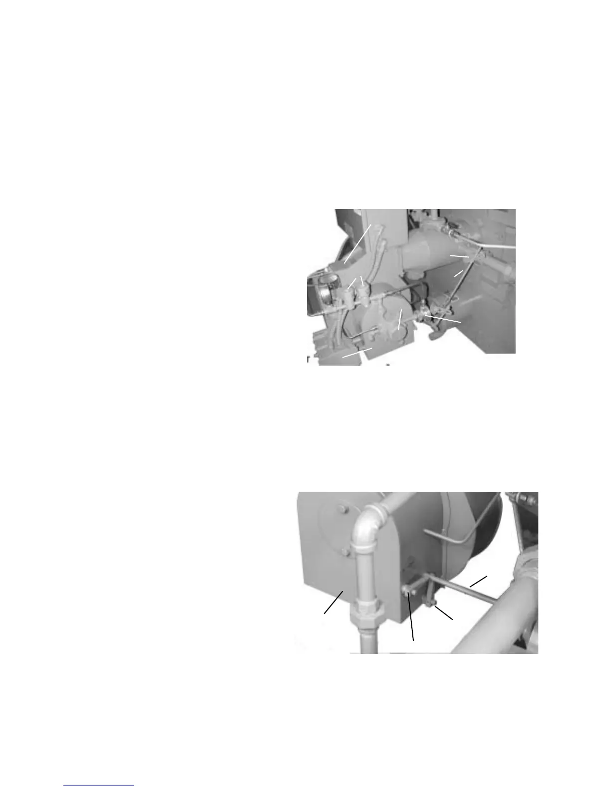
11. Gas Butterfly Valve (Figure 2-5). The gas butterfly valve
regulates the flow rate of natural gas into the burner. The
gas butterfly valve is connected, by linkage and a jack
shaft, to the modulating motor, which provides the rotary
motion to open and close the valve.
12. Valve Linkage (Figure 2-5). The valve linkage transfers
the modulating motion from the main air shutter shaft to
the fuel metering valve shafts. The linkage provides a
means of adjustment to maintain the correct fuel-to-air
ratio over the entire burner operating range, high fire to
low fire.
13. Oil Metering Valve (Figure 2-5). The oil metering valve
regulates the flow rate of oil into the burner. The oil
metering valve is connected by linkage and a jack shaft
to the modulating motor, which provides the rotary
motion to open and close the valve.
14. Oil Pump (Figure 2-5). The oil pump provided for oil
burning is coupled to an extension of the combustion air
fan shaft.
15. Modulating Motor (Figure 2-5). The modulating motor is
coupled to the jack shaft that operates the main air shutter
and the fuel valve linkages. The modulating motor
produces the torque and rotary positioning required for
firing rate control.
16. Oil Solenoid Valves (Figure 2-5). The oil solenoid
valves are in series and downstream of the oil metering
valve in the supply line to the oil burner assembly. Two
valves are provided. These valves are simultaneously
energized to open and release fuel oil to the burner. The
valves close to stop combustion when oil is the fuel.
17. Rear Cap (Figure 2-5). The rear cap contains the locking
setscrew for adjustment of the diffuser relative to the air
baffle, and also the flame scanner for the flame
safeguard. The rear cap must be removed to enable
removal of the oil gun assembly.
18. Low-Fire Shutter (Figure 2-6). The low-fire shutter
provides a means to set the correct combustion air flow
rate for low-fire operation. The handle indicates relative
shutter position.
19. High-Fire Shutter (Figure 2-6). The high-fire shutter
provides a means to set the correct combustion air flow
rate for high-fire operation. The handle indicates relative
shutter position.
A. GAS BUTTERFLY VALVE
B. VALVE LINKAGE
C. OIL METERING VALVE
D. OIL PUMP
E. MODULATING MOTOR
F. OIL SOLENOID VALVES
G. REAR CAP
A
B
C
E
Figure 2-5: Oil And Gas Piping To Burner
A
B
C
Figure 2-6: Airbox and Shutters
D
F
G
D
20. Airbox (Figure 2-6). The airbox is attached to the inlet side of
the fan housing. It serves as the inlet and flow regulating
valve for combustion air, and houses the combustion air
control shutters.
21. Main Air Shutter Shaft (Figure 2-6). The main air shutter
modulates the combustion air between low fire and high fire
conditions. The shaft connects the modulating motor to the
main air shutter and to the fuel valve linkage assemblies.