Chapter 5 STARTING AND OPERATING INSTRUCTIONS
5-14 750-177
13. Check intermediate positions for proper combustion.
Adjust the linkage, as required, to match the fuel and air
rates indicated in Table 5-2.
14. Modulate and recheck combustion air at different firing
rates. When large adjustments are made at one rate, they
may adversely affect settings at another rate.
E. BURNER ADJUSTMENTS,
COMBINATION GAS AND OIL
Note: The operator must consider and allow
for normal variations in air and fuel, which
would reduce the range of excessive
oxygen in the flue gas accordingly.
This section of the manual presents procedures to be followed
for initial startup of a combination ProFire burner.
!
DANGER
CAUTION
This burner is designed to burn only those fuels
shown on the burner data plate. Burning fuels
not specified on the data plate could cause
damage to the equipment.
These procedures assume that the pre-startup tasks,
checklists, and adjustments have been completed, and that the
boiler system is prepared for initial startup. All necessary test
equipment should be available on site.
In general, the combination fueled system is to be started first
using oil, because, as a fuel, oil has a greater combustion air
requirement than natural gas. After being completely
adjusted for oil combustion, the burner is re-started and
adjusted using natural gas as fuel. Combustion adjustment of
the combination burner for natural gas involves balancing the
input gas rates only against the existing flow of combustion
air, as established initially for oil-firing.
Do not readjust the
air shutters when tuning the combination burner for
combustion of natural gas.
!
DANGER
WARNING
Attempting initial burner startup with
insufficient knowledge of the equipment
and startup procedures can result in
serious damage. The operator must be
totally familiar with the entire startup and
adjustment process before attempting to
operate the burner.
CONTROLS SETUP. Complete the following system control
setup steps before beginning the combination burner startup
procedure:
1. Check the linkages to confirm that they are securely
fastened and ready for operation (see Figures 3-2 and 3-
4).
NOTE: The linkages have been factory-set and
tested, although they may require fine tuning for
the specific application. If the linkage is not in
place, or if the setting has been lost, install the
linkage in accordance with Figures 5-9 and 5-
11.
2. Place the burner switch in the OFF position.
3. Place the Modulating Mode switch in the MANUAL
position.
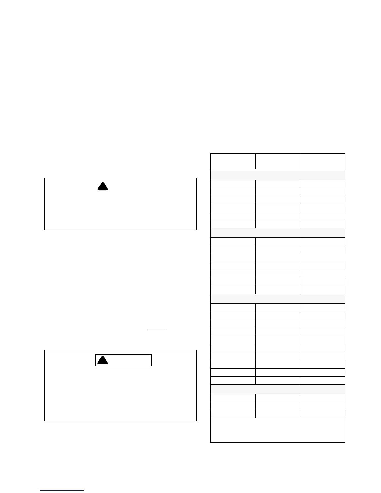
INPUT
(MMBtu/hr)
MINIMUM O2
(%)
MAXIMUM O2
(%)
SIZE 1
0.7 N/A N/A
0.9 4.0 9.5
1.0 4.0 9.5
1.5 2.5 8.0
2.0 2.0 5.0
2.5 2.0 5.0
SIZE 2
1.5 4.0 10.0
2.0 4.0 10.0
2.5 3.5 10.0
3.0 3.0 9.5
3.5 3.0 7.0
4.0 3.0 5.0
4.5 3.0 5.0
SIZE 3
4.5 3.0 8.5
5.0 3.0 8.5
5.5 2.5 8.0
6.0 2.5 7.0
6.5 2.0 6.0
7.0 2.0 5.0
7.5 2.0 5.0
8.0 2.0 5.0
8.5 2.0 5.0
9.0 2.0 4.5
SIZE 4
10.0 3.0 5.0
11.0 3.0 5.0
12.0 3.0 4.5
Note: Table presents the maximum recommended range of operating levels
of excess oxygen in the flue gas for various burner sizes, operating at given
levels of light oil input to the burner. Data is valid for conditions at standard
atmospheric temperature and pressure. Results will vary under environmen-
tal conditions differing from standard.
Table 5-2: Recommended Stack Gas O
2
Concentration At Various Rates (Light Oil)