STARTING AND OPERATING INSTRUCTIONS Chapter 5
750-177 5-13
7. Set the high-fire fuel input pressure to match the
maximum oil pressure specification on the burner data
plate by adjusting the fuel input. The oil metering valve
should be in the fully closed position and the fuel
pressure should be set to the nameplate pressure.
NOTE: Refer to the curves of burner input
rate versus oil pressure (Figures 5-12, 5-13
and 5-14) to determine the oil input rate at
any given oil pressure for the specific
installed burner nozzle size. Nozzle capacity
is stamped on the nozzle body.
8.
9. Size 4 burners utilize return flow nozzles rather than
simplex nozzlesused in smaller sizes. See Table 5-3 for
nozzle size and oil pressure.
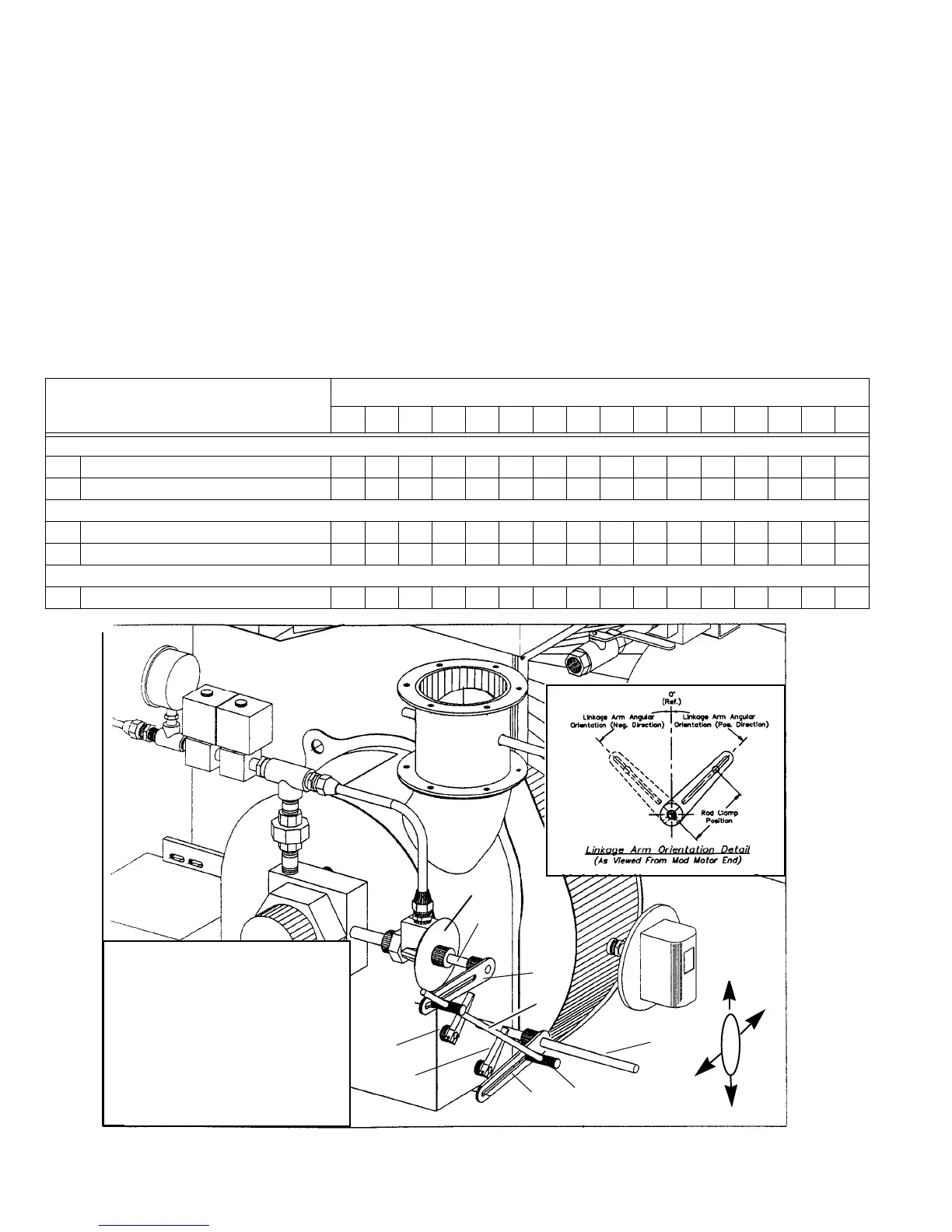
10. Adjust the high-fire shutter to obtain the correct excess
air level (see Figure 5-11 for the adjustment location).
11. Modulate to low fire using the manual flame control in
accordance with Table 5-2.
12. Set the proper fuel input for low fire by adjusting the
linkage to drive the oil metering valve to the proper
position (see Figure 5-11 for oil metering valve linkage
adjustments).
4
2
7
1
8
9
5
LEGEND
1. MAIN SHAFT OIL CONTROLLER ARM
2. OIL CONTROLLER ARM
3. OIL VALVE METERING SCALE
4. OIL METERING VALVE SHAFT
5. MAIN AIR SHUTTER SHAFT
6. LINKAGE CONNECTING ROD
7. BALL JOINTS
8. HIGH-FIRE AIR SHUTTER HANDLE
9. LOW-FIRE AIR SHUTTER HANDLE
6
DESCRIPTION
INPUT RATE MMBtu/hr.
1.5 2.0 2.5 3.0 3.5 4.0 4.5 5.0 5.5 6.0 7.0 8.0 9.0 10.0 11.0 12.0
LINKAGE ARM ANGULAR ORIENTATION (IN DEGREES)
1 Main Shaft Oil Controller Arm 88 94 106 110 110 115 115 125 120 120 120 120 120 130 125 105
2 Oil Controller Arm 806652654575751409590905555507050
ROD CLAMP POSITION FROM CENTER POINT (IN INCHES)
1 Main Shaft Oil Controller Arm 2.38 3.38 2.56 3.25 3.253.003.002.253.253.253.503.253.504.254.254.25
2 Oil Controller Arm 2.13 2.63 1.81 2.25 2.25 3.503.503.502.752.753.002.002.003.0 2.752.25
OIL VALVE SETTING (METERING SCALE ON VALVE)
3 Oil Valve Metering Scale setting 13 15.5 17.5 14 13.5 11 10 6 12.5 9.5 10 17.5 17 ***
0°
90°
180°
3
Figure 5-11: Oil Fired System Control Linkage
* Factory Set