Chapter 5 STARTING AND OPERATING INSTRUCTIONS
5-12 750-177
CONTROLS SETUP. Complete the following combination
system control setup steps before beginning the oil-fired
burner startup procedure:
1. Check the linkages to confirm that they are securely
fastened and ready for operation (see Figure 5-11).
NOTE: The linkages have been factory-set
and tested, although they may require fine
adjustment for the specific application. If
the linkage is not in place, or if the setting
has been lost, install the linkage in
accordance with Figure 5-11.
2. Place the burner switch to the OFF position.
3. Place the Manual/Auto mode switch to the MANUAL
position.
4. Place the manual flame control potentiometer to the
CLOSED (low-fire) position.
5. Check the presetting of the air shutters. (If the linkage is
loose and no pre-settings are available, start with the
shutter in the full open position).
6. When a gas pilot is used, open the valve in the gas pilot
line.
STARTUP. Proceed with initial startup of the oil-fired system
as follows:
1. Turn on the electrical power for the burner, boiler, and
related components.
2. Verify that the oil metering valve is nearly open.
NOTE: Opening the oil metering valve
reduces oil flow to the burner.
3. Turn the burner switch on. This will start the blower
motor and initiate the prepurge sequence.
4. When the prepurge sequence ends, the pilot valve will
open. The pilot flame should be visible from the viewing
window.
NOTE: If the pilot is established, the flame
safeguard will energize the two oil solenoid
valves (this is accompanied by a click from
the solenoid valves and illumination of the
FUEL VALVE light) and the oil burner should
ignite on low-fire.
5. After the main flame has been established, the oil
pressure entering the burner nozzle should be read (by
reading the oil pressure gauge downstream of the oil
solenoid valves) to get an initial estimate of the fuel oil
input rate. Oil pressure should be about 80 psi when
operating at low-fire. Adjust the oil metering valve if the
actual pressure is not within the range of 80 to 90 psi.
6. Operate the boiler at low fire until it is thoroughly
warmed. Then, modulate to high fire by turning the
manual flame potentiometer to the OPEN position. This
will cause the oil metering valve to close, resulting in an
increase in the oil pressure feeding the burner nozzle.
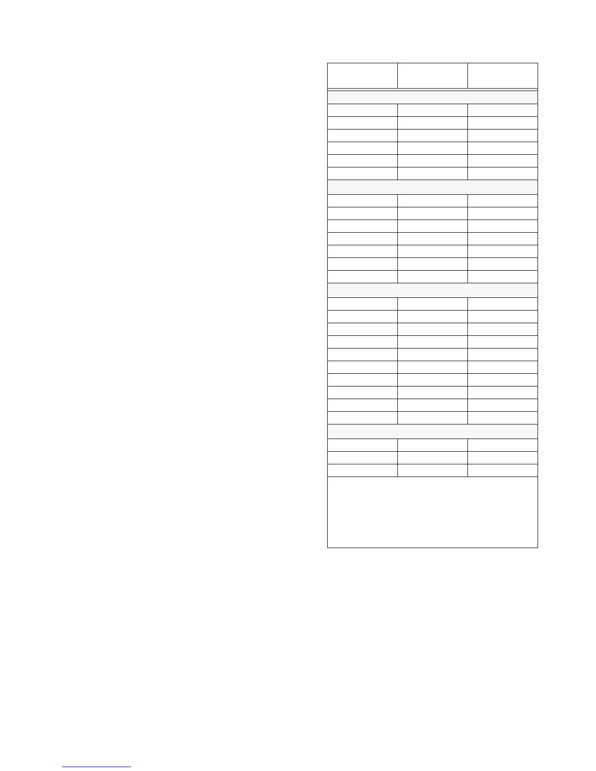
Check the excess air in the flue gas (see Table 5-2 for
acceptable O
2
levels), while modulating to high-fire.
Adjust the oil pressure if needed.
INPUT
(MMBtu/hr)
MINIMUM O
2
(%)
MAXIMUM O
2
(%)
SIZE 1
0.7 3.0 9.0
0.9 3.0 9.0
1.0 3.0 9.0
1.5 2.5 9.0
2.0 2.0 5.5
2.5 2.0 5.0
SIZE 2
1.5 3.0 8.0
2.0 3.0 8.0
2.5 3.0 8.0
3.0 3.0 8.0
3.5 3.0 7.0
4.0 3.0 5.0
4.5 3.0 5.0
SIZE 3
4.5 2.5 7.5
5.0 2.5 7.5
5.5 2.5 7.0
6.0 2.5 6.5
6.5 2.5 6.0
7.0 2.5 5.5
7.5 2.5 5.0
8.0 2.5 5.0
8.5 2.5 5.0
9.0 2.0 4.5
SIZE 4
10.0 2.5 5.0
11.0 2.5 5.0
12.0 2.0 4.5
Note: Table presents the maximum recommended range
of operating levels of excess oxygen in the flue gas for
various burner sizes, operating at given levels of natural
gas input to the burner. Data is valid for conditions at stan-
dard atmospheric temperature and pressure. Results will
vary under environmental conditions differing from stan-
dard.
Table 5-1: Recommended Stack Gas 0
2
Concentration at Various Rates (Natural Gas)