Chapter 6 Adjustment Procedures
6-6 750-177
I. MODULATING TEMPERATURE
CONTROL (Hot Water)
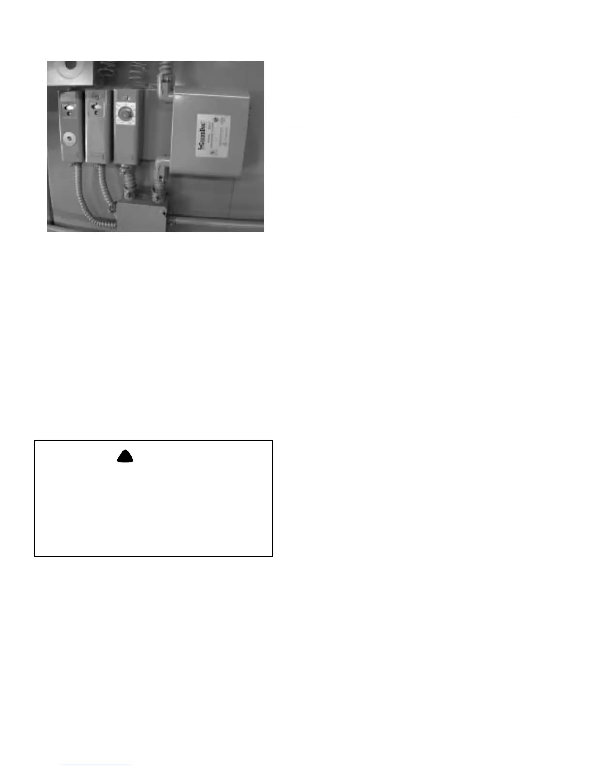
Turn the knob on the front of the case (see Figure 6-6) until
the pointer indicates the desired setpoint temperature. The
desired set point is the center point of a proportional range.
The control has a 3 to 30° differential and may be adjusted to
vary the temperature range within which modulating action is
desired. With the cover off, turn the adjustment wheel until
pointer indicates desired range.
!
DANGER
CAUTION
To prevent burner shutdown at other than
low-fire setting adjust modulating tempera
-
ture control to modulate low fire BEFORE
operating limit temperature control shuts
off burner. Failure to follow these instruc
-
tions could result in damage to the equip-
ment.
J. OPERATING LIMIT
TEMP ER AT UR E CONTRO L
(Hot Water)
Set “cut-out” (burner off) temperature on the scale by
inserting a screwdriver through the cover opening to engage
the slotted head adjusting screw (see Figure 6-6). The “cut-
in” (burner on) temperature is the cut-out temperature
MINUS the differential. The differential is adjusted from 5 to
30° F.
K. HIGH LIMIT TEMPERATURE
CONTROL (Hot Water)
Set the “cut-out” (burner off) temperature on scale using the
adjusting screw. The control will break the circuit and
lock
out on a rise in water temperature above the setting. The
setting should be sufficiently above the operating limit
temperature to avoid unnecessary shutdowns. The control
requires manual resetting after tripping on a temperature
increase. To reset, allow the water temperature to drop below
the cut-out setting less differential, and then press the manual
reset button.
L. LOW WATER CUTOFF DEVICES
(Steam and Hot Water)
No adjustment is required since LWCO controls are preset by
the original manufacturer. However, if the water level is not
maintained, inspect the devices immediately and replace as
required.
M. COMBUSTION AIR PROVING
SWITCH
Air pressure against the diaphragm actuates the switch which,
when made, completes a circuit to prove the presence of
combustion air. Since the pressure of the combustion air is at
its minimum value when the damper is full closed, the switch
should be adjusted under that situation. It should be set
slightly below the minimum pressure, but not too close to that
point to cause nuisance shutdowns.
The run/test switch on the program relay should be set to
TEST. Turn the burner switch on. The blower will start
(provided that all limit circuits are completed) and the
programmer will remain in the low-fire (damper closed)
portion of the prepurge.
Slowly turn down the air switch adjusting screw until it
breaks the circuit. Here the programmer will lock out and
must be manually reset before it can be restarted. Add a half
turn or so to the adjusting screw to remake its circuit.
Recycle the program relay to be sure that normal operation is
obtained. Return the test switch to the RUN position.
N. GAS PILOT FLAME ADJUSTMENT
The size of the gas pilot flame is regulated by adjusting the
gas flow through the pilot gas regulator. The flame must be
sufficient to ignite the main flame and to be seen by the flame
detector. But an extremely large flame is not required. An
overly rich flame can cause sooting or carbon buildup on the
igniting electrode. Too small a flame can cause ignition
problems.
1. HIGH LIMIT TEMPERATURE CONTROL LIMIT
2.
OPERATING LIMIT TEMPERATURE CONTROL
3. MODULATING TEMPERATURE CONTROL
123
Figure 6-6: Hot Water Controls