STARTING AND OPERATING INSTRUCTIONS Chapter 5
750-177 5-5
B. STARTUP PROCEDURES
PRESTART TASKS AND CHECKLIST - ALL
FUELS
Before proceeding with system startup and adjustment, be
sure that overall installation is complete. Review the boiler
operating and installation manual set carefully to verify that
the boiler is properly set up for operation. Check that all
shipped-loose items (those items not installed when shipped)
have been correctly installed. Verify the supply of fuel. Check
to make sure the burner is wired as shown on the wiring
diagram. Ensure that all control wiring terminals are tight.
Complete the following checklist in preparation for system
startup:
• Confirm that the fuel and electrical connections have
been completed in accordance with the applicable codes
and insurance requirements (if necessary), and that con
-
nections comply with the piping schematic and wiring
diagram.
• Check the combustion air fan motor for correct rota-
tional direction.
• Check that the boiler is filled with water to the proper
level, and that all circulating pumps (hot water units) are
correctly installed and operational.
• Verify that there is proper gas pressure at the gas train,
if this is a gas or combination burner. See the burner
specification plate (Figure 5-8) for minimum and maxi
-
mum natural gas pressure requirements.
• For oil burners confirm that the oil tank is adequately
filled with the correct grade of fuel oil, and that any iso
-
lation valves in the supply and return lines are open.
• Check that the flame safeguard has been properly in-
stalled inside the control panel.
• Provide the following test equipment on site:
1) Combustion analyzer for O
2
.
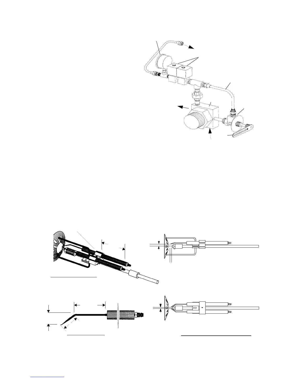
OIL PRESSURE
GAUGE
OIL SOLENOID VALVES
OIL BYPASS
OIL
VALVE
OIL PUMP
OIL TO BURNER
OIL SUPPLY INLET
EXCESS OIL
RETURN TO TANK
Figure 5-4: Oil Piping Schematic
TUBING
METERING
OIL
VALVE
ARM
SPARK IGNITION CLAMP
MOUNTED ELECTRODES
SET GAP 1/8
SET GAP 7/16”
ELECTRODES - TO NOZZLE POSITION
ELECTRODE SHAPE
19/32
1
1-15/16
3-1/2
1
Figure 5-5: Direct Spark Ignition Electrode Adjustment Dimensions
ABOVE CENTER
LINE OF NOZZLE
BETWEEN
ELECTRODES
SET GAP 1/4”
AHEAD OF NOZZLE