Chapter 5 STARTING AND OPERATING INSTRUCTIONS
5-6 750-177
!
DANGER
WARNING
Attempting initial burner startup with
insufficient knowledge of the equipment
and startup procedures can result in
serious damage to the equipment. The
operator must be totally familiar with the
entire startup and adjustment process
before attempting to operate the burner.
Failure to follow these instructions can
result in seoious personal injury or death
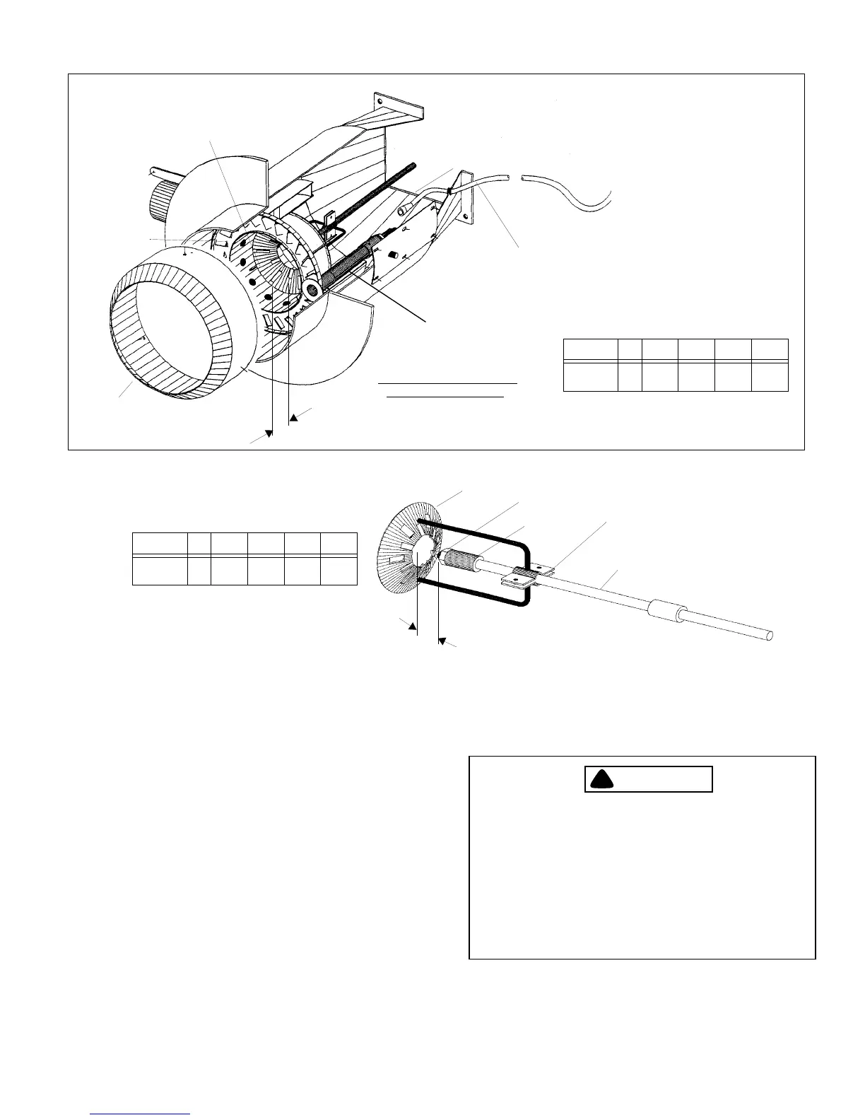
AIR
DIFFUSER
OIL PIPE
HIGH VOLTAGE
IGNITER CABLE
B
DIFFUSER - TO - AIR BAFFLE
ALIGNMENT DIMENSION
BAFFLE
GAS ELECTRIC
PILOT ASSEMBLY
Figure 5-6: Blast Tube
CHOKE CONE
ITEM KEY SIZE 1 SIZE 2 SIZE 3 SIZE 4
Diffuser To
Air Baffle
B 1-11/16 2-1/4 3-1/8 3-1/8
DIFFUSER
OIL NOZZLE
OIL NOZZLE
DIFFUSER CLAMP
OIL PIPE
A
ADAPTER
ITEM KEY SIZE 1 SIZE 2 SIZE 3 SIZE 4
Nozzle To
Diffuser
A 5/8 11/16 3/4 1-1/16
Figure 5-7: Nozzle / Diffuser / Air Baffle Alignment
2) U-tube manometer, or pressure gauge, to measure
gas pressures (main and pilot).
3) Inclined manometer to measure draft pressures.
4) Smoke spot tester for oil fired units. CO analyzer
for gas fired burners.
5) Voltmeter.
6) Thermometers and thermocouples.