Chapter 5 STARTING AND OPERATING INSTRUCTIONS
5-4 750-177
4. Carefully install the adjusted nozzle/diffuser assembly
into the burner. Then re-connect the oil supply and high-
voltage power cable to the assembly.
5. The diffuser-to-air baffle dimension “B” must now be
checked and adjusted (see Figure 5-6 for correct
dimension). Check and adjust to dimension “B” as
follows:
A.Open the burner mounting door on the boiler. Swing
the burner out to expose the diffuser and air baffle.
B. Measure the distance between the leading edge of the
diffuser and the front face of the inner ring on the air
baffle assembly.
C. If adjustment is required, loosen the burner pipe
locking setscrew (located on the rear cap at the top of
the fan housing) and slide the burner pipe in or out to
achieve the correct “B” dimension.
D.Tighten the oil pipe locking setscrew securely.
E. Swing the burner and mounting door into the closed
position on the boiler and fasten the door securely.
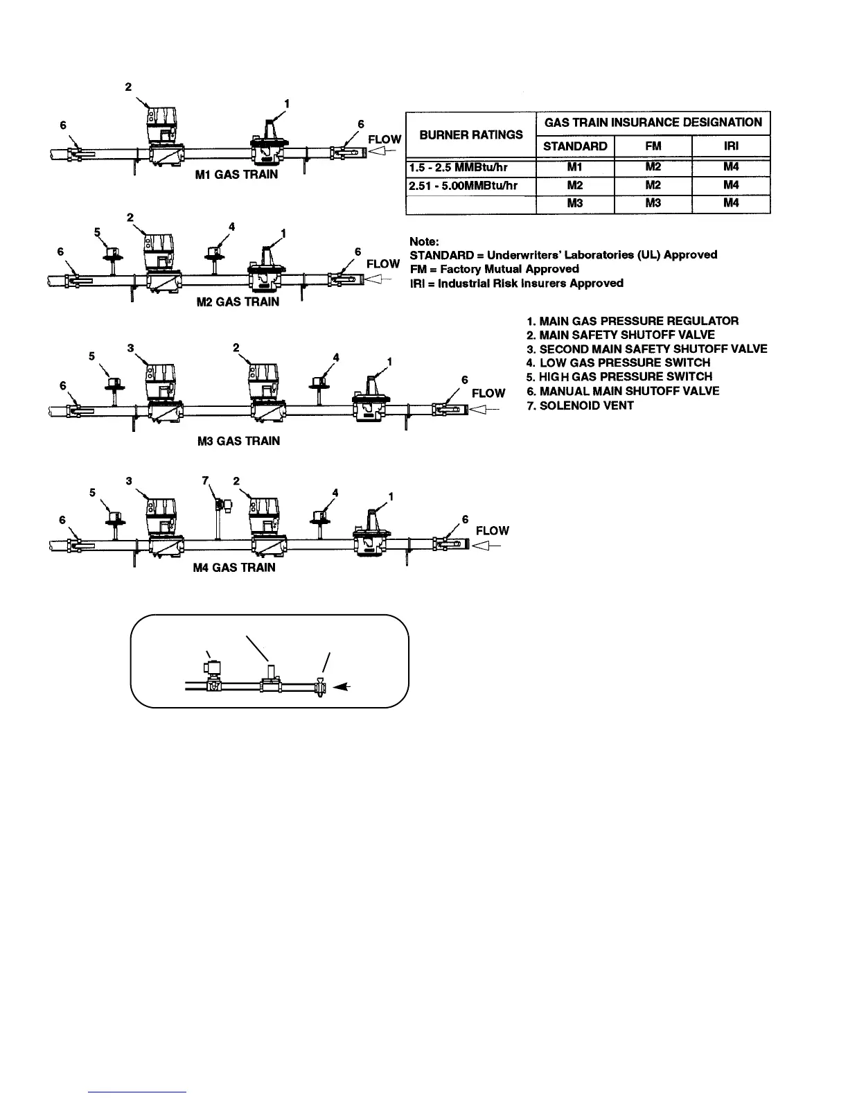
FLOW
MANUAL
PRESSURE REGULATOR
SOLENOID VALVE
Figure 5-3: Pilot Gas Train
PILOT STOPCOCK
B. Rotate and slide each electrode in the clamp, as necessary,
to achieve the correct position relative to the burner tip.
C. Tighten the locking screws securely to lock the electrodes
in position. Apply a lock-tight type compound to the
screws before tightening.
3. Refer to Figure 5-7 and measure the distance from the tip of
the nozzle to the diffuser (Dimension “A”). If necessary,
adjust the position of the diffuser as follows:
A.Loosen the locking screws on the diffuser clamp.
B. Slide the diffuser clamp along the length of the burner pipe
until the correct dimension is achieved.
C. Tighten the diffuser clamp securely to the burner pipe.
Apply a Lock-tight type compound to the screws before
tightening.
Note: Gas train
configurations are subject
to change. The above
configurations reflect
components at the date of
this Operation and
Maintenance manual
publication date.
5.01 - 12.00 MMBtu/hr