STARTING AND OPERATING INSTRUCTIONS Chapter 5
750-177 5-3
!
DANGER
WARNING
Inadvertent burner operation can cause
serious injury, or death. Do not perform
maintenance on a burner without first
disabling the electrical power supply. Lock
out and tag the electrical power supply to
prevent inadvertent burner startup during
checkout or maintenance activities. Failure
to follow these instructions could result in
serious personal injury or death.
A.Lock out and tag the electrical power supply to the
burner to prevent inadvertent operation during
checkout or maintenance activities.
B. Disconnect the high-voltage power supply from the
oil-spark-ignition electrodes (if installed).
C. Disconnect the oil piping from the end of the blast
tube.
D.Remove the fasteners that secure the nozzle/diffuser
assembly to the top of the fan housing, and remove the
nozzle/diffuser assembly from the burner.
2. Measure the position and gap of the pilot electrodes, and
compare these to the dimensions shown in Figure 5-5. If
necessary, adjust the position of the electrodes relative to
the nozzle as follows:
A.Loosen the locking screws on the spark ignition clamp
assembly (Figure 5-5).
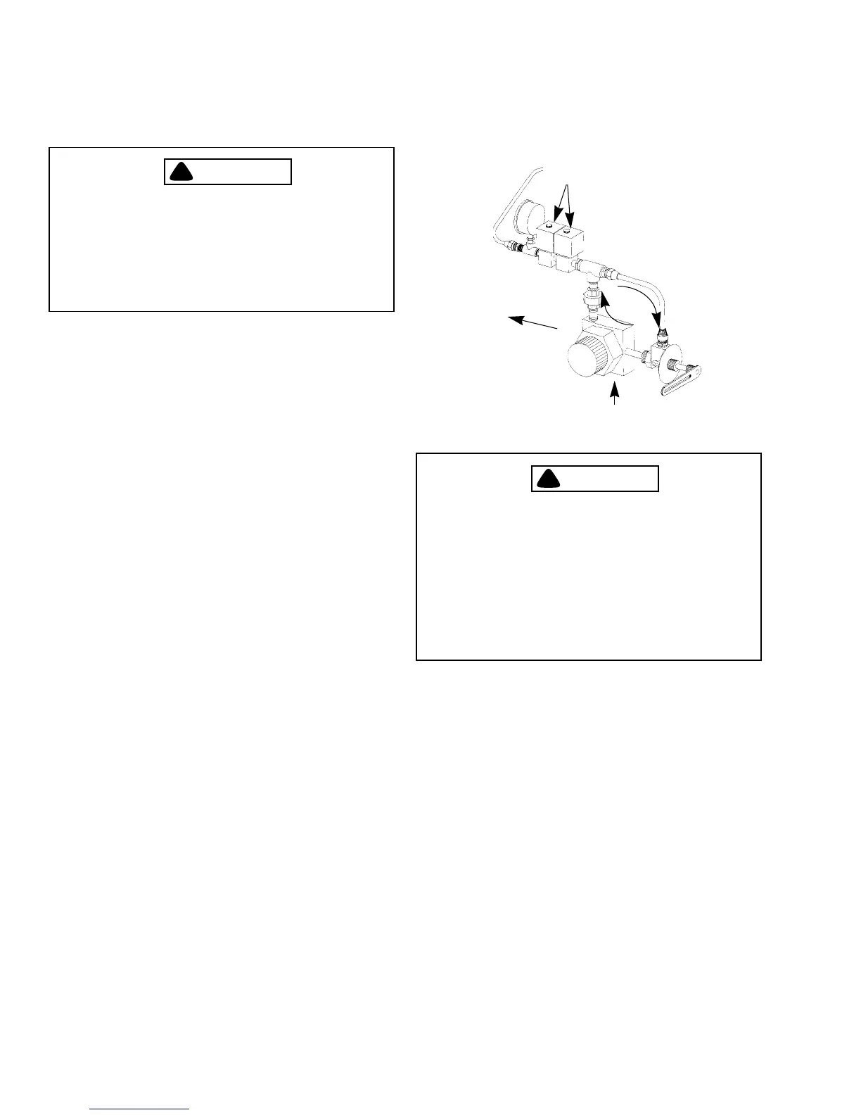
Figure 5-2: Oil Pump Circulation
OIL SOLENOID
VALVES (CLOSED)
OIL SUPPLY INLET
EXCESS OIL RETURN TO
TANK
OIL CIRCULATION
BURNER OFF FAN ON
3. ELECTRICAL REQUIREMENTS AND
CONNECTIONS
!
DANGER
WARNING
Shut off and lock out all electrical power to
the burner before performing any service or
maintenance that requires removal of
electrical equipment covers or component
parts. Failure to follow these instructions
could result in serious personal injury or
death.
Verify that all electrical power supplies and branch circuit
wiring are sized in accordance with the electrical loads shown
on the specification plate on the side of the burner control
cabinet (Figure 5-8). Check system interlocks, control
interfaces, and any additional remote controls against the
system schematic and wiring diagram. Refer to the Cleaver-
Brooks wiring diagram supplied with the burner for specific
requirements. Verify that all supply wiring terminations are
tight.
4. LINKAGE CONNECTIONS
Inspect all linkages for damage and/or loosening during
shipment. All fasteners must be secure for safe operation. All
connections must be correctly positioned and tightened
(Figure 5-9 and 5-11). Apply a lock-tight type compound to
any fasteners after adjustment.
5. BURNER SETTINGS
To ensure reliable and safe burner performance, the location
and gap setting of the electrodes for the direct-spark igniters,
and the relative positions of the burner nozzle, diffuser, and
air baffle components must be correctly set (Figures 5-5, 5-6
and 5-7). Normally these items are preset at the factory, but
must be checked prior to placing the burner into initial
service, or after conducting any service work that may have
altered their positions.
The nozzle/diffuser assembly must be removed from inside
the burner to enable measurement and adjustment of the oil-
spark-ignition electrodes (furnished only on oil burners) and
the nozzle relative to the diffuser.
1. Remove the nozzle/diffuser assembly as follows: